Equipment for cutting leftover materials on edges of wooden barrels
A technology for cutting corners and edges, which is applied to sawing equipment, clamping angle irons, wood processing appliances, etc. It can solve hidden dangers and safety problems, and achieve the effect of reducing the amount of operation
- Summary
- Abstract
- Description
- Claims
- Application Information
AI Technical Summary
Problems solved by technology
Method used
Image
Examples
Embodiment 1
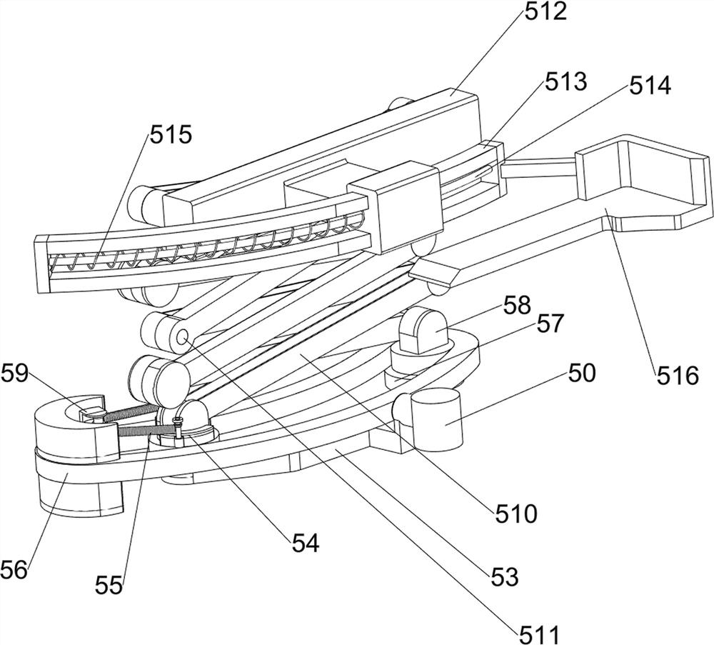
[0065] A kind of equipment for cutting corner material on the edge of wooden barrels, such as figure 1 and figure 2 As shown, it includes a base plate 1 , a cutting mechanism 2 and a rotating mechanism 3 , the cutting mechanism 2 is arranged on the top of the base plate 1 , and the rotating mechanism 3 is connected to the cutting mechanism 2 .
[0066] The staff can place the wooden barrel on the rotating mechanism 3, start the operation of the rotating mechanism 3 to drive the barrel to rotate and rotate at the same time, the operation of the rotating mechanism 3 drives the cutting mechanism 2 to cut the edge of the wooden barrel, and stop the rotating mechanism 3 after the cutting is completed To operate, just collect the barrels.
Embodiment 2
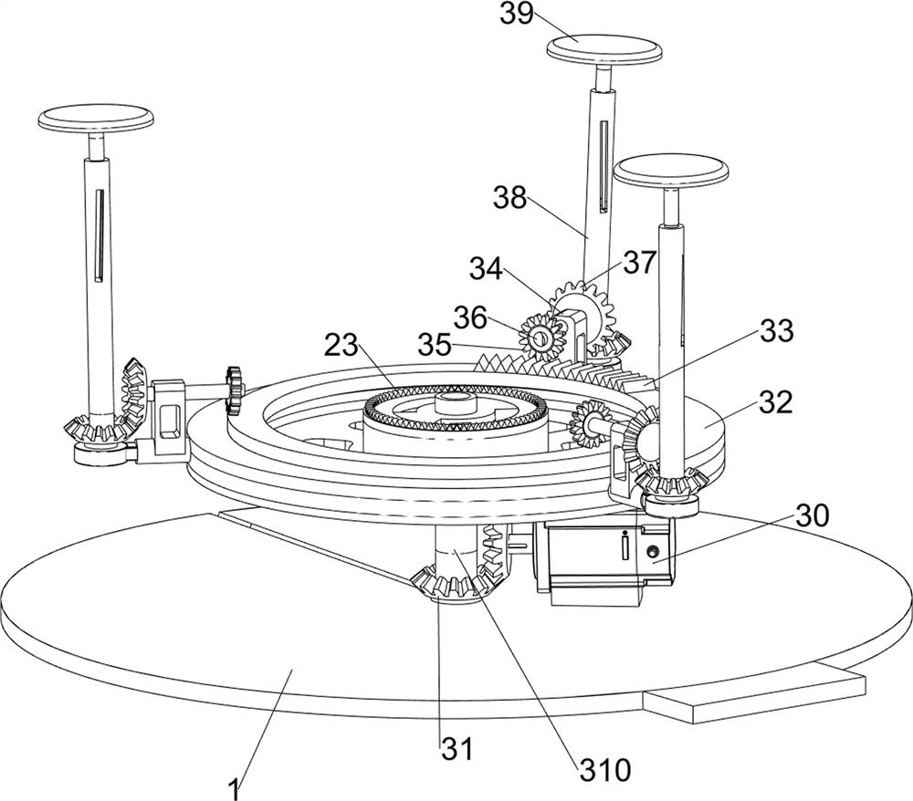
[0068] On the basis of Example 1, such as image 3 and Figure 4 As shown, the rotating mechanism 3 includes a servo motor 30, a second bevel gear set 31, a turntable 32, a missing tooth ring 33, a first support block 34, a second gear 35, a third rotating shaft 36, a third bevel gear set 37, The fourth rotating shaft 38, the material receiving tray 39 and the fifth rotating shaft 310, the top of the bottom plate 1 is rotatably connected with the fifth rotating shaft 310, the top of the fifth rotating shaft 310 is connected with the turntable 32, the outer side of the top of the turntable 32 is provided with a missing tooth ring 33, the turntable 32 Three first support blocks 34 are evenly arranged on the outer side, and the upper part of the first support block 34 is connected with a third rotating shaft 36 in a rotational manner, and the inner end of the third rotating shaft 36 is connected with a second gear 35, and the second gear 35 is connected with the missing tooth rin...
Embodiment 3
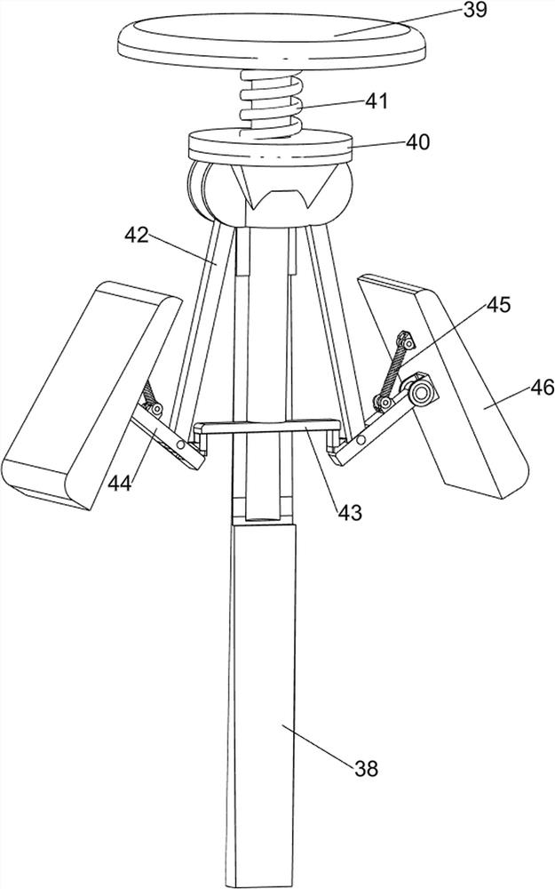
[0072] On the basis of Example 2, such as Figure 5 to Figure 7 As shown, a clamping mechanism 4 is also included, and the clamping mechanism 4 includes a first fixed block 40, a first spring 41, a first movable rod 42, a fixed rod 43, a first rotating rod 44, a second spring 45 and clamps Block 46, the top of the fourth rotating shaft 38 is connected with the first fixed block 40, the first spring 41 is connected between the top of the first fixed block 40 and the material receiving plate 39, and the first movable rod is hinged on both sides of the first fixed block 40 42, the bottom of the material receiving tray 39 is connected with a fixed rod 43, the first rotating rod 44 is hinged on both sides of the fixed rod 43, the first rotating rod 44 is connected with the first movable rod 42 in a rotational manner, and the outer ends of the first rotating rod 44 are A clamping block 46 is connected in a rotational manner, and a second spring 45 is connected between the clamping b...
PUM
 Abstract
Description
Claims
Application Information
 - R&D
- Intellectual Property
- Life Sciences
- Materials
- Tech Scout
- Unparalleled Data Quality
- Higher Quality Content
- 60% Fewer Hallucinations
Browse by: Latest US Patents, China's latest patents, Technical Efficacy Thesaurus, Application Domain, Technology Topic, Popular Technical Reports.
© 2025 PatSnap. All rights reserved.Legal|Privacy policy|Modern Slavery Act Transparency Statement|Sitemap|About US| Contact US: help@patsnap.com


