Steel pipe cutting device for high-end equipment manufacturing

A technology for cutting devices and steel pipes, applied in the direction of pipe shearing devices, shearing devices, and accessories of shearing machines, etc., can solve the problems of uncontrollable cutting length and poor fixation, and achieve the effect of reducing safety hazards and preventing deviation

Active Publication Date: 2021-03-26
佛山市盾牌金属制品有限公司
View PDF17 Cites 4 Cited by
  • Summary
  • Abstract
  • Description
  • Claims
  • Application Information

AI Technical Summary

Problems solved by technology

[0004] In order to overcome the shortcomings of the existing technology that people need to hold a cutter to cut sequentially, and the cutting length cannot be controlled, it is not easy to fix, and there are potential safety hazards. Fixed and safe steel pipe cutting device for high-end equipment manufacturing

Method used


Image

  • Steel pipe cutting device for high-end equipment manufacturing
  • Steel pipe cutting device for high-end equipment manufacturing
  • Steel pipe cutting device for high-end equipment manufacturing

Examples


Embodiment 1

[0024] A steel pipe cutting device for high-end equipment manufacturing, such as Figure 1 to Figure 3 As shown, it includes a bottom plate 1, a base 2, a cutting mechanism 3 and a steel pipe flow mechanism 4, which is provided with a bottom plate 1 and a base 2, the base 2 is located on the right side below the bottom plate 1, and the right side of the top of the base 2 is provided with a cutting mechanism 3, the bottom plate 1. A steel pipe flow direction mechanism 4 is provided on the top.

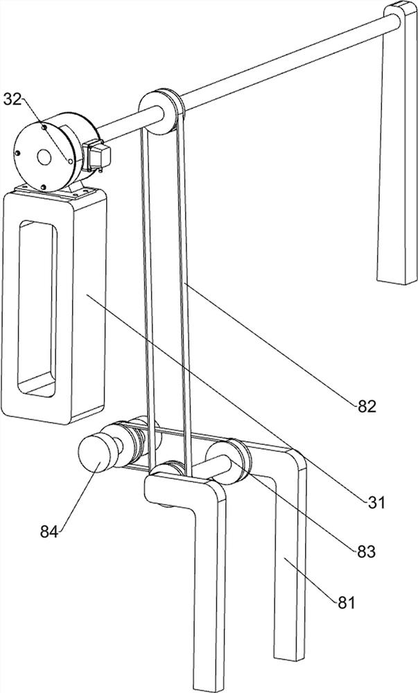
[0025] The cutting mechanism 3 includes a mounting base 31, a servo motor 32, a disc 33, a first connecting rod 34, a second connecting rod 35, a third connecting rod 36 and a cutting tool 37, and the right front side of the top of the base 2 is provided with a mounting base 31, The top of the mounting seat 31 is provided with a servo motor 32, the output shaft of the servo motor 32 is connected with a disc 33, the right side of the base 2 top is rotatably connected with a second connec...

Embodiment 2

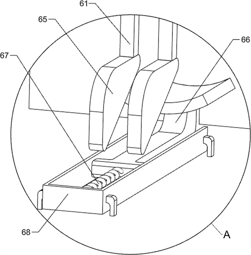
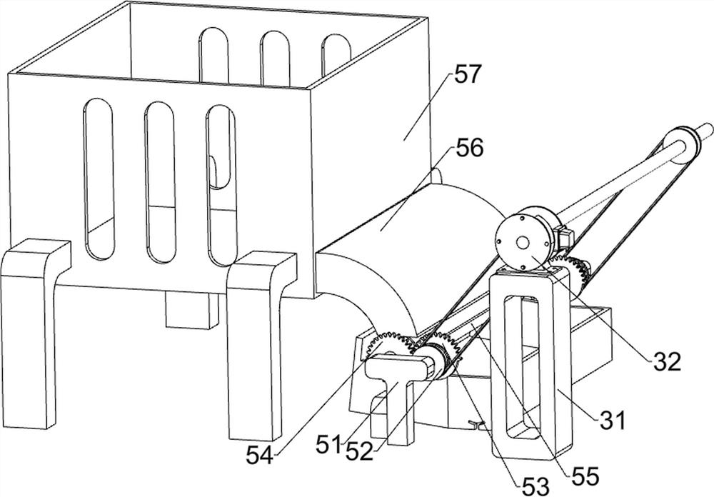
[0029] On the basis of Example 1, such as Figure 4 to Figure 7 As shown, an automatic feed mechanism 5 is also included, and the automatic feed mechanism 5 includes a mounting frame 51, a first pulley assembly 52, a sector gear 53, a transmission gear 54, a feed wheel 55, a feed chute 56 and a steel pipe to place Frame 57, the right side of base 2 top is symmetrically provided with mounting frame 51, is equipped with sector gear 53 and transmission gear 54 on the mounting frame 51, and sector gear 53 meshes with transmission gear 54, the rotating shaft of sector gear 53 and servo motor The first pulley assembly 52 is connected between the output shafts of 32, the feed wheel 55 is connected between the rotating shafts of the transmission gear 54, the steel pipe placement frame 57 is connected on the left side of the top of the base 2, and the steel pipe placement frame 57 bottom right side is connected with a The feed trough plate 56 is located above the feed wheel 55 .

[00...


PUM


Abstract

The invention relates to a steel pipe cutting device, in particular to a steel pipe cutting device for high-end equipment manufacturing. According to the steel pipe cutting device for high-end equipment manufacturing, a cutter does not need to be held by a person, a steel pipe is fixed through a machine, and safety is guaranteed. The steel pipe cutting device for high-end equipment manufacturing comprises a bottom plate, a base, a cutting mechanism and a steel pipe flow direction mechanism, wherein the bottom plate is located on one side of the base; the cutting mechanism is arranged on one side of the top of the base; and the steel pipe flow direction mechanism is arranged at the top of the bottom plate. By arranging the cutting mechanism, a cutting tool is driven to move up and down to cut the steel pipe, and the basic functions of the device are achieved; and by arranging an automatic feeding mechanism and the steel pipe flow direction mechanism, a feeding wheel is driven to rotateto intermittently convey the steel pipes in cooperation with cutting.

Description

technical field [0001] The invention relates to a steel pipe cutting device, in particular to a steel pipe cutting device used for high-end equipment manufacturing. Background technique [0002] Steel is a general term for iron-carbon alloys with a carbon content between 0.02% and 2.11%. Steel has become one of the most used materials in the world due to its low price and reliable performance. One of the forms is steel pipe, which is used to transport fluid and powdery solids, exchange heat, make mechanical parts and containers, and is also an economical steel, commonly used in the construction industry For piling, load-bearing, drainage, etc., the length of the steel pipe needs to be determined in advance according to the customer's requirements. [0003] In the prior art, the steel pipes need to be laid horizontally on the ground, and the workers cut the steel pipes sequentially with hand-held cutters. At the same time, it is difficult to control the cutting length by han...

Claims


Application Information

Patent Timeline
Patent Type & Authority Applications(China)
IPC IPC(8): B23P23/04B23D21/00B23D33/02
CPCB23P23/04B23D21/00B23D33/02Y02P70/10
Inventor 欧阳红燕
Owner 佛山市盾牌金属制品有限公司
Why Eureka
Try Eureka