
Post-earthquake cement pavement crack monitoring device

A cement pavement and monitoring device technology, applied to measuring devices, roads, roads, etc., can solve the problems of unable to slow down the continuous expansion of cracks on the road surface, soil subsidence, single function, etc.

Active Publication Date: 2021-04-20
山西省地震局
View PDF9 Cites 0 Cited by
  • Summary
  • Abstract
  • Description
  • Claims
  • Application Information

AI Technical Summary

Problems solved by technology

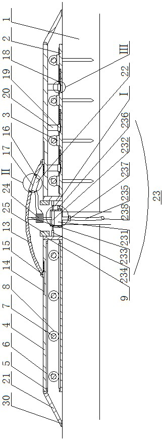
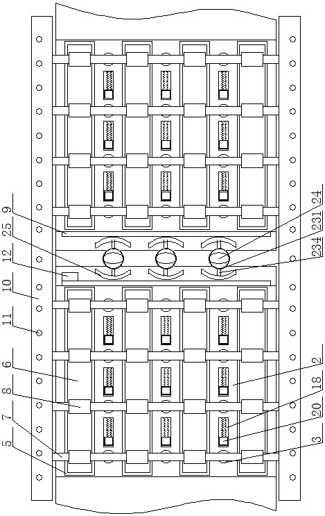
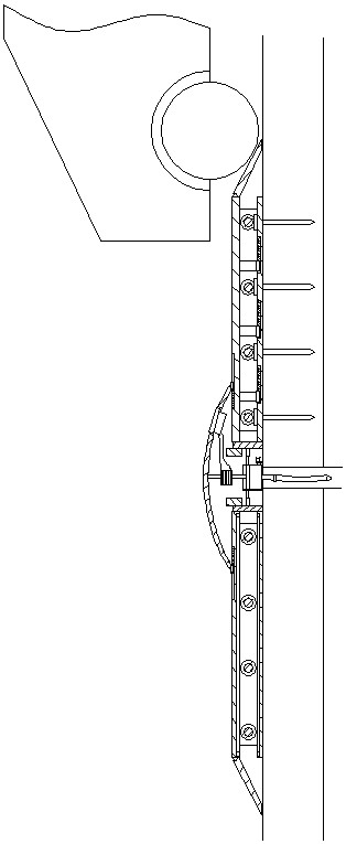
[0002] After the earthquake, many road surfaces will be damaged to varying degrees and cracks will appear. However, even if there are cracks on many roads, considering that many cracks do not affect the normal use of the road, and traffic needs to be restored as much as possible during the earthquake, it is generally not The road surface cracks will be repaired immediately, but the road cracks will be monitored at any time while the road is open to traffic, and the road will be repaired until the crack width affects normal traffic. The traditional cement pavement crack monitoring device has a single function. When monitoring pavement cracks, it is impossible to protect the cracks, nor can it slow down the continued expansion of pavement cracks. Therefore, in the case of vehicles coming and going and rain washing, the width of the cracks will expand rapidly, and even the soil at the cracks will collapse. , which is not conducive to the use of roads after the earthquake

Method used


Image

  • Post-earthquake cement pavement crack monitoring device
  • Post-earthquake cement pavement crack monitoring device
  • Post-earthquake cement pavement crack monitoring device

Examples


Embodiment Construction

[0012] In order to make the purpose, technical solutions and advantages of the embodiments of the present invention clearer, the technical solutions in the embodiments of the present invention will be clearly and completely described below in conjunction with the drawings in the embodiments of the present invention. Obviously, the described embodiments It is a part of embodiments of the present invention, but not all embodiments. Based on the embodiments of the present invention, all other embodiments obtained by persons of ordinary skill in the art without creative efforts fall within the protection scope of the present invention.

[0013]A post-earthquake cement pavement crack monitoring device, as shown in the figure, includes a pavement 1 with cracks, fixed plates 2 are arranged on both sides of the pavement 1 corresponding to the cracks, and the fixed plates 2 are attached to the road surface 1 and passed through the first fixing nails 3. It is fixedly connected with the ...


PUM


Abstract

The invention discloses a post-earthquake cement pavement crack monitoring device. The device comprises a pavement with cracks, wherein fixing plates are arranged on the two sides of the cracks, supporting plates are arranged above the fixing plates, strip-shaped grooves are formed in the side faces of the fixing plates and the supporting plates, rotating shafts are arranged between the fixing plates and the corresponding supporting plates, limiting plates are connected to one ends of the fixing plates, transverse rods are arranged on the two sides of the pavement and distance sensors arranged on the side faces of the limiting plates; an elastic arc-shaped plate is arranged above the supporting plate, a first through hole is formed in the elastic arc-shaped plate, a warning lamp is arranged in the first through hole, the opposite end of the supporting plate is connected with an overlapping plate, the lower side of the warning lamp is connected with a rechargeable battery, and a drainage device is arranged on the road surface corresponding to cracks. The device is advantaged in that impact force, friction force and pressure on the device in the automobile running process are used for driving the left road surface and the right road surface to get close to each other, the expansion speed of cracks can be decreased in the earthquake period, cracks can be repaired in the earthquake rest period, the service life of the damaged road surface is prolonged, and safety is improved; and the device can also drain water in the cracks so that the loss after an earthquake is reduced.

Description

technical field [0001] The invention belongs to the field of road surface crack monitoring devices, in particular to a post-earthquake cement pavement crack monitoring device. Background technique [0002] After the earthquake, many road surfaces will be damaged to varying degrees and cracks will appear. However, even if there are cracks on many roads, considering that many cracks do not affect the normal use of the road, and traffic needs to be restored as much as possible during the earthquake, it is generally not The road surface cracks will be repaired immediately, but the road cracks will be monitored at any time while the road is open to traffic, and the road will be repaired until the crack width affects normal traffic. The traditional cement pavement crack monitoring device has a single function. When monitoring pavement cracks, it is impossible to protect the cracks, nor can it slow down the continued expansion of pavement cracks. Therefore, in the case of vehicles ...

Claims


Application Information

Patent Timeline
Patent Type & Authority Applications(China)
IPC IPC(8): E01C11/22E01F9/50E01C11/02G01B21/02
Inventor 曾金艳扈桂让闫小兵
Owner 山西省地震局
Learn More