
Wall auxiliary device for building construction

A kind of auxiliary equipment and construction technology, which is applied in the direction of construction, construction components on-site preparation, mechanical equipment, etc. It can solve the problems of high physical exertion of workers, low efficiency, troublesome movement of scaffolding, etc.

Inactive Publication Date: 2021-04-20
耿洪玉
View PDF8 Cites 0 Cited by
  • Summary
  • Abstract
  • Description
  • Claims
  • Application Information

AI Technical Summary

Problems solved by technology

[0002] With the rapid development of my country's economy and society, the development of the construction industry is changing with each passing day. At the same time, higher requirements are put forward for the construction industry, which is mainly reflected in the requirement to save costs and improve production efficiency. From the current point of view, in the process of building walls, mainly rely on Manually, the workers not only consume a lot of physical strength, but also have low efficiency
[0003] In the prior art, mechanical structures such as scaffolding are usually used when building walls and painting walls, but it is troublesome to move the scaffolding and needs to be disassembled and transported, and when working on some relatively old walls, not only need to It has the effect of supporting and protecting the wall, and it also needs to work on higher places. There is a lack of such auxiliary equipment in the existing technology

Method used


Image

  • Wall auxiliary device for building construction
  • Wall auxiliary device for building construction
  • Wall auxiliary device for building construction

Examples


Embodiment

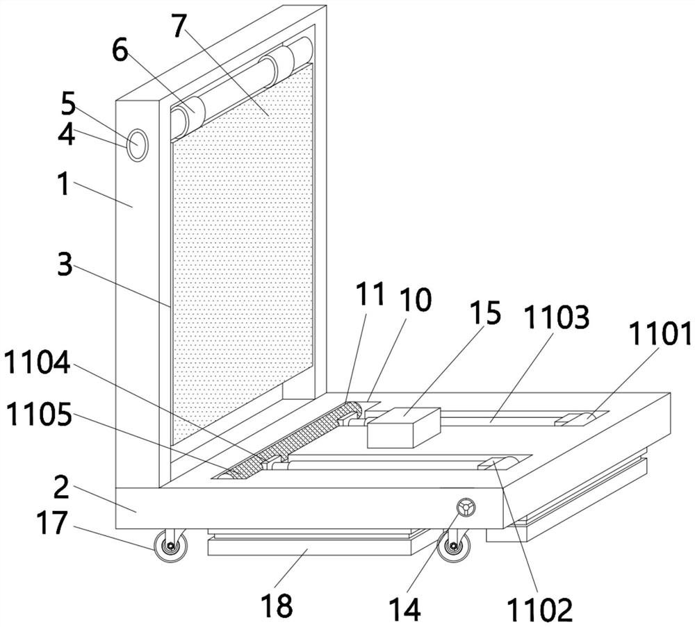
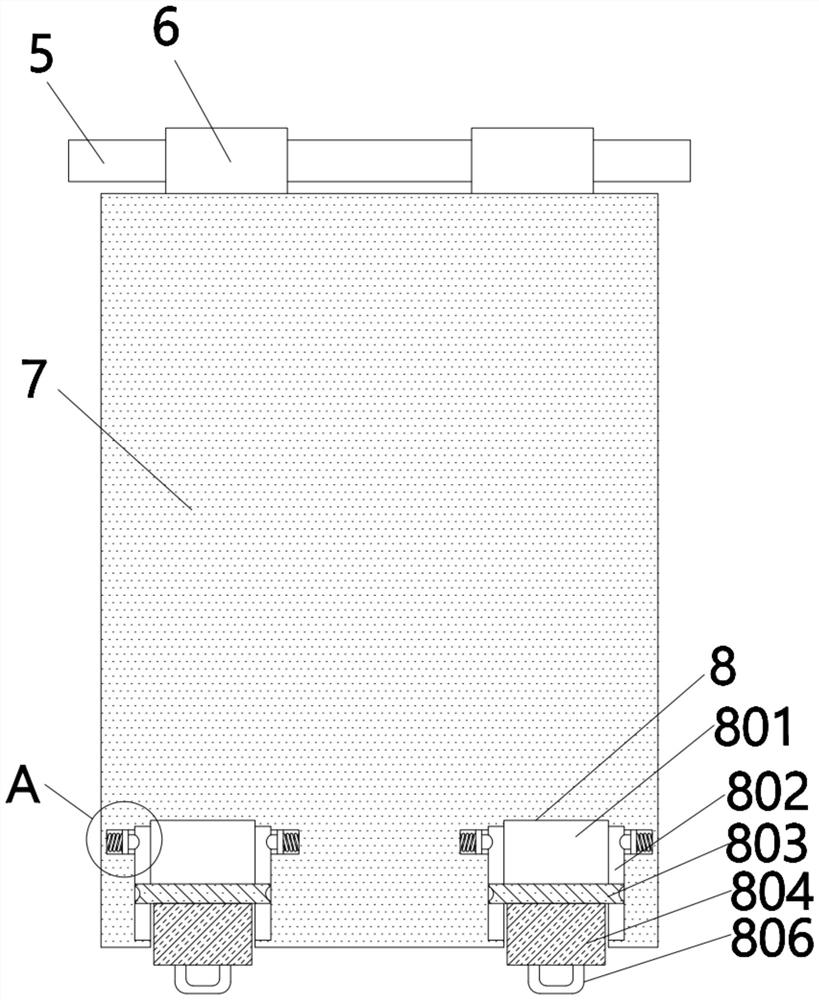
[0034] see figure 1 , a kind of wall auxiliary equipment for building construction, comprising a side support plate 1 and a fixing seat 2, the side support plate 1 is fixedly connected to the top left side of the fixing seat 2, and the right side surface of the side support plate 1 is provided with Rectangular slot 3, the upper end of the rectangular slot 3 is located on the front and back of the side support plate 1, and a round hole 4 is provided. The inside of the round hole 4 is fixedly connected with a rotating shaft 5, and the surface of the rotating shaft 5 is connected with a rotating shaft. 6, the bottom of the two rotating parts 6 is fixedly connected with a support plate 7, the support plate 7 is located inside the rectangular groove 3, the bottom of the support plate 7 is provided with a snap-in mechanism 8, and the snap-in mechanism The inside of 8 is provided with a limit mechanism 9, and the top surface of the fixed seat 2 is provided with a placement groove 10,...


PUM


Abstract

The invention discloses a wall auxiliary device for building construction. The wall auxiliary device comprises a side supporting plate and a fixing seat, wherein the side supporting plate is fixedly connected to the left side of the top of the fixing seat, a rectangular groove is formed in the surface of the right side of the side supporting plate, and round holes are formed in the upper end of the rectangular groove and located in the front surface and the back surface of the side supporting plate. A connecting plate drives a pulley to ascend and descend through an arranged transmission lifting mechanism, so that the pulley exceeds a damping mechanism to be in contact with the ground, and the device is convenient to move and does not need to be disassembled; when some old walls are operated, the device is moved to the edge of the wall through sliding, so that the side supporting plate is tightly attached to the wall; and then a supporting mechanism is taken out of a containing groove and is vertically placed, so that a clamping mechanism in the supporting plate extends out from the interior, a semicircular clamping cylinder in the clamping mechanism is clamped with a transverse rod, and a locking structure is controlled through an adjusting knob to lock a rotating rod, so that the device can be used for carrying out operation on some high positions.

Description

technical field [0001] The invention relates to the field of building construction, and more specifically relates to a wall auxiliary device for building construction. Background technique [0002] With the rapid development of my country's economy and society, the development of the construction industry is changing with each passing day. At the same time, higher requirements are put forward for the construction industry, which is mainly reflected in the requirement to save costs and improve production efficiency. From the current point of view, in the process of building walls, mainly rely on Manually, the workers not only consume a lot of physical strength, but also have low efficiency. [0003] In the prior art, mechanical structures such as scaffolding are usually used when building walls and painting walls, but it is troublesome to move the scaffolding and needs to be disassembled and transported, and when working on some relatively old walls, not only need to To suppo...

Claims


Application Information

Patent Timeline
Patent Type & Authority Applications(China)
IPC IPC(8): E04G1/15E04G1/18E04G1/24E04G5/00E04G5/02E04G5/08E04G25/00F16F15/067
Inventor 耿洪玉
Owner 耿洪玉
Learn More