
Shock absorption robot used in using process of pulse generator and shock absorption method

A pulse generator and robot technology, applied in springs/shock absorbers, mechanical equipment, vibration suppression adjustment, etc., can solve the problems of loose parts and shortened service life, and achieve the effect of improving the effect of shock absorption

Inactive Publication Date: 2021-04-20
南京罗朗智合电子科技有限公司
View PDF0 Cites 1 Cited by
  • Summary
  • Abstract
  • Description
  • Claims
  • Application Information

AI Technical Summary

Problems solved by technology

[0003] At present, mobile operation is more popular. In the process of mobile operation, the vehicle will move forward and the staff will use the pulse generator in the vehicle. There are many advantages in mobile operation, but there are also many disadvantages in mobile operation, such as When the vehicle is moving forward, if the road surface is uneven, the staff inside the vehicle and the pulse generator in use will vibrate, and the long-term vibration of the pulse generator will cause its internal parts to loose, thereby shortening its service life, in view of the above problems, the present invention designs a shock-absorbing robot used in the use of the pulse generator, so as to solve the above problems

Method used


Image

  • Shock absorption robot used in using process of pulse generator and shock absorption method
  • Shock absorption robot used in using process of pulse generator and shock absorption method
  • Shock absorption robot used in using process of pulse generator and shock absorption method

Examples


Embodiment Construction

[0037] The present invention will be further described below in conjunction with the examples.

[0038] The following examples are used to illustrate the present invention, but cannot be used to limit the protection scope of the present invention. The conditions in the embodiment can be further adjusted according to the specific conditions, and the simple improvement of the method of the present invention under the premise of the concept of the present invention belongs to the protection scope of the present invention.

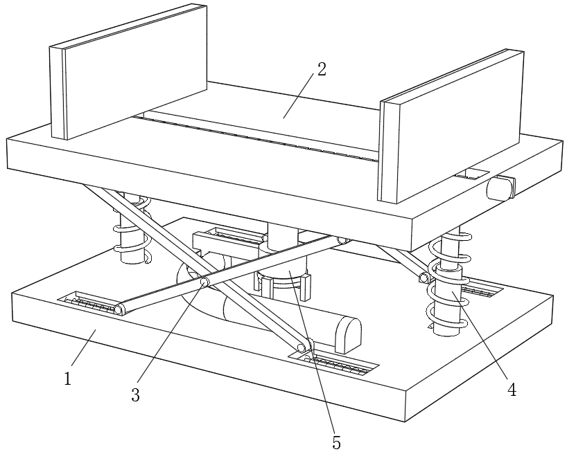
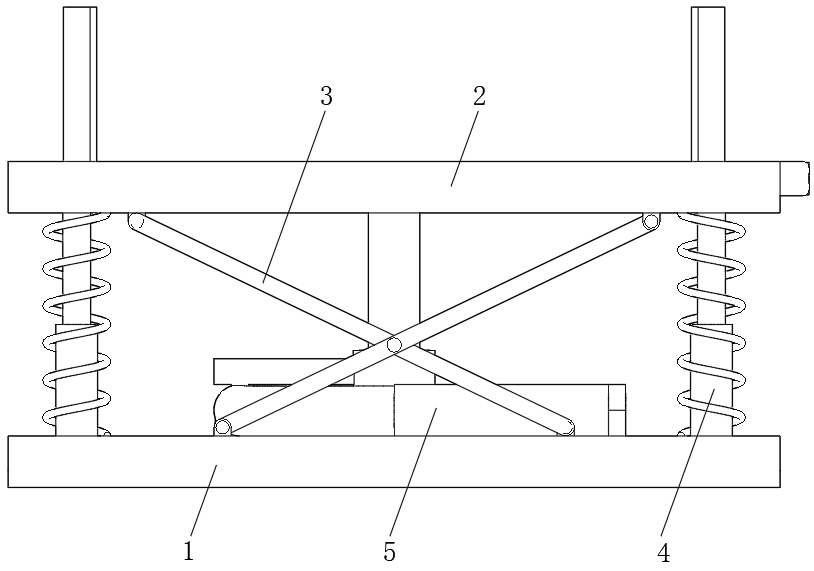
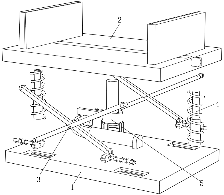
[0039] see Figure 1-12 , the present invention provides a vibration-absorbing robot used in the use of a pulse generator, comprising a bottom component 1, a top clamping component 2 is arranged above the bottom component 1, and a top clamping component 2 is arranged between the bottom component 1 and the top clamping component 2. Two first shock absorbing mechanisms 3, two second shock absorbing mechanisms 4 and one third shock absorbing mechanism 5, the two...


PUM


Abstract

The invention discloses a shock absorption robot used in the using process of a pulse generator, and belongs to the technical field of pulse generators. The shock absorption robot comprises a bottom assembly, a top clamping assembly is arranged above the bottom assembly, two first shock absorption mechanisms, two second shock absorption mechanisms and a third shock absorption mechanism are arranged between the bottom assembly and the top clamping assembly, the two first shock absorption mechanisms are located on the front side and the rear side of the bottom assembly and the front side and the rear side of the top clamping assembly correspondingly, the two second shock absorption mechanisms are located on the left side and the right side of the bottom assembly and the left side and the right side of the top clamping assembly correspondingly, the third shock absorption mechanism is located between the bottom assembly and the top clamping assembly, a pulse generator body is clamped above the top clamping assembly, and the bottom assembly comprises a fixed bottom plate. Through combined use of the first shock absorption mechanisms, the second shock absorption mechanisms and the third shock absorption mechanism, the pulse generator body can be subjected to shock absorption for three times, and therefore the shock absorption effect is greatly improved, and the shock absorption robot can be easily pushed to the market.

Description

technical field [0001] The invention belongs to the technical field of pulse generators, and in particular relates to a shock-absorbing robot used in the use of pulse generators. Background technique [0002] The pulse generator is a system used to generate signals and generate electrical test signal instruments with required parameters. According to its signal waveform, it is divided into four categories. ①Sine signal generator. It is mainly used to measure frequency characteristics, nonlinear distortion, gain and sensitivity of circuits and systems. According to their different performances and uses, they can be subdivided into low-frequency (20 Hz to 10 MHz) signal generators, high-frequency (100 kHz to 300 MHz) signal generators, microwave signal generators, frequency sweep and program-controlled signal generators, Frequency synthesis signal generator, etc.; ② function (waveform) signal generator. It can generate some specific periodic time function waveforms (sine w...

Claims


Application Information

Patent Timeline
Patent Type & Authority Applications(China)
IPC IPC(8): F16F15/067B60R11/00
Inventor 曾敬芬
Owner 南京罗朗智合电子科技有限公司
Learn More