A self-powered dynamic weighing device and working method based on magnetostrictive material

A magnetostrictive material and dynamic weighing technology, which is applied to piezoelectric effect/electrostrictive or magnetostrictive motors, measuring devices, electromechanical devices, etc., can solve the problem of large equipment footprint, cumbersome installation, and road excavation Large area and other problems, to achieve the effect of simple installation, high sensitivity and small structure

Active Publication Date: 2022-05-03
HANGZHOU DIANZI UNIV
View PDF0 Cites 0 Cited by
  • Summary
  • Abstract
  • Description
  • Claims
  • Application Information

AI Technical Summary

Problems solved by technology

[0003] However, the existing dynamic weighing systems, such as: resistive dynamic weighing device, bent plate dynamic weighing device, etc., all have problems such as large equipment footprint, cumbersome installation, and large excavation area on the road surface for embedding wires.

Method used


Image

  • A self-powered dynamic weighing device and working method based on magnetostrictive material
  • A self-powered dynamic weighing device and working method based on magnetostrictive material
  • A self-powered dynamic weighing device and working method based on magnetostrictive material

Examples


Embodiment 1

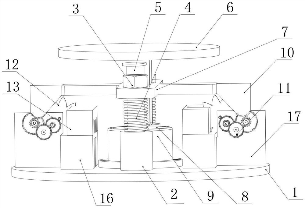
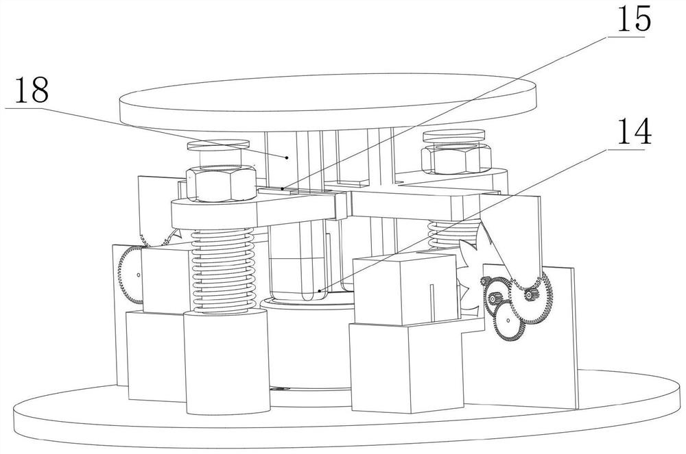
[0032] Such as figure 1 and 2 As shown, a piezoelectric dynamic weighing device based on magnetostrictive materials includes a base 1, a support plate 6, a load-bearing column 18, a guide assembly, a weighing assembly and a self-powered assembly. Bearing column 18 adopts polymer nylon rubber. The weighing assembly includes a piezoelectric sensor 8 and a piezoelectric sheet holder 9 . Bolt holes are drilled on the ears extending from the bottom of the piezoelectric sheet holder 9, and the center position of the piezoelectric sheet holder 9 and the top surface of the base 1 is fixed with bolts. The top of the piezoelectric sheet holder 9 is provided with a sensor installation groove. A piezoelectric sensor 8 with a detection surface facing up is installed in the sensor installation groove. The piezoelectric sensor 8 includes four piezoelectric sheets connected in series; the signal output line of the piezoelectric sensor 8 is connected to the signal processing module. The s...

Embodiment 2

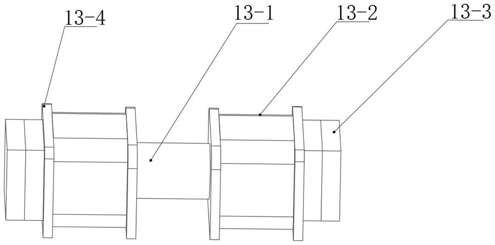
[0047] The difference between this embodiment and Embodiment 1 is that: the side of the blade of the impeller 12 is parallel to the axis of the impeller 12, so that the blade is easier to bend after touching the magnetostrictive rod 13-1, reducing capacity loss.

Embodiment 3

[0049] The difference between this embodiment and Embodiment 1 is that the final output gear is connected to the output shaft through a one-way bearing; so that the final output gear can only drive the output shaft to rotate in one direction, thereby avoiding the Output rotating shaft and impeller 12 continue to rotate.


PUM


Abstract

The invention discloses a self-powered dynamic weighing device based on a magnetostrictive material and a working method. The invention includes a base, a support plate, a load-bearing column, a guide assembly, a weighing assembly and a self-powered assembly. The weighing assembly is mounted on the base. The guide assembly is installed on the base; a crossbeam capable of sliding up and down is arranged in the guide assembly. The load-bearing column is fixed to the beam, the bottom end is against the weighing assembly, and the top end is fixed to the support plate. One or more energy supply arms are arranged on the beam. The energy supply arm is made of elastic material. The number of self-powered components corresponds to the number of powered arms. The self-powered assembly includes a pusher plate, a transmission assembly, an impeller, and a magnetostrictive energy harvesting module. The magnetostrictive energy harvesting module is installed on the base, including magnetostrictive rods, induction coils and permanent magnets. In the working method of the present invention, the time when each wheel is detected is used to measure and calculate parameters such as the speed of the vehicle, the wheelbase, the number of axles, etc., so as to realize the comprehensive data collection of road vehicles.

Description

technical field [0001] The patent of the present invention relates to the technical field of vehicle dynamic weighing, in particular to a self-powered dynamic weighing device based on magnetostrictive materials and a working method. Background technique [0002] In order to protect the road surface and bridges from being damaged by overweight vehicles, more and more roads are now carrying out weighing inspections on vehicles. The current mainstream weighing devices are divided into dynamic weighing and static weighing. Compared with dynamic weighing, static weighing is not affected by external force, so its error is relatively small, but it cannot measure its single axle weight. And when the vehicle is weighed, the passing speed of the lane decreases, resulting in a significant reduction in lane traffic efficiency and unnecessary traffic jams. The dynamic weighing is to complete the weighing detection when the vehicle is running normally, which saves the detection time and ...

Claims


Application Information

Patent Timeline
Patent Type & Authority Patents(China)
IPC IPC(8): G01G19/03G01G23/00G01D21/02H02N2/18H02K35/04H02J7/34
Inventor 王云何流鲍秉德燕国良王翔黄依凡
Owner HANGZHOU DIANZI UNIV
Why Eureka
Try Eureka