
Wire fixing frame for computer host

A fixed frame and computer technology, applied in the direction of electrical components, etc., can solve the problems of time-consuming and laborious removal of wires, scattered on the ground, and cluttered arrangement.

Inactive Publication Date: 2021-04-20
西安大富宇航科技有限公司
View PDF0 Cites 0 Cited by
  • Summary
  • Abstract
  • Description
  • Claims
  • Application Information

AI Technical Summary

Problems solved by technology

[0004] In view of the above situation, in order to overcome the defects of the prior art, the present invention provides a wire fixing frame for the computer mainframe, which effectively solves the problem that the current clamping clamp is difficult to solve the problem that the data line in the computer room is too long, the arrangement is messy or even scattered on the ground The problem, and the clips are generally disposable, it takes time and effort to dismantle the wires, causing great inconvenience to the maintenance personnel

Method used


Image

  • Wire fixing frame for computer host
  • Wire fixing frame for computer host
  • Wire fixing frame for computer host

Examples


Embodiment 1

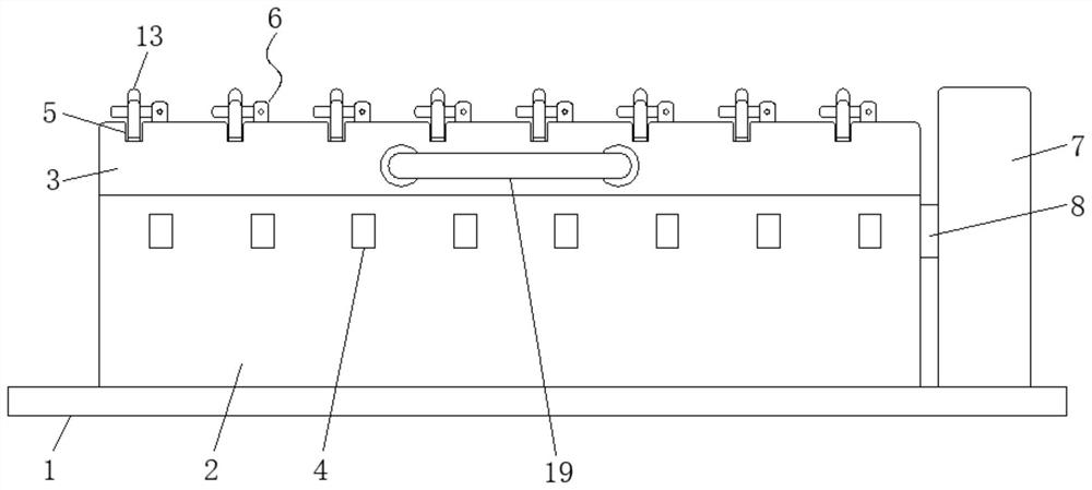
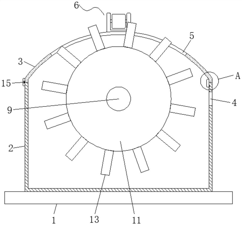
[0023] Embodiment one, by figure 1 , figure 2 with Figure 4 Given, the present invention includes a mounting plate 1, a bottom box 2 is fixedly mounted on the top of the mounting plate 1, a top cover 3 is movably mounted on the top of the bottom box 2, and eight connection ports 4 are equidistantly provided on one side of the bottom box 2 , through the setting of the connection port 4, the data line can be effectively connected with the rotating disk 11, and the top of the top cover 3 is equidistantly provided with eight rotating grooves 5, and through the setting of the rotating groove 5, the rotating rod 13 can be effectively One side of the eight rotating slots 5 and the top of the top cover 3 are all equipped with a fixing mechanism 6. Through the setting of the fixing mechanism 6, no rotating disk 11 can be rotated independently. One end of the top of the mounting plate 1 A protective box 7 is fixedly installed, and a first casing 8 is fixedly connected between the pr...

Embodiment 2

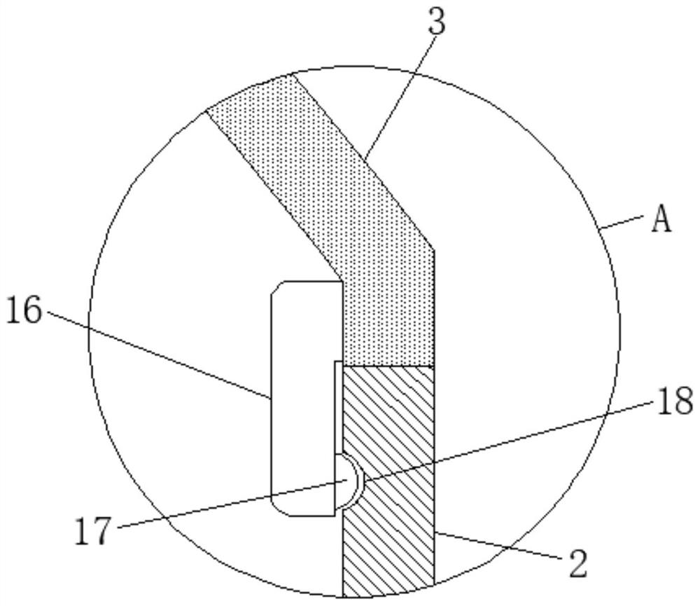
[0024] Embodiment two, on the basis of embodiment one, by figure 2 with image 3 Given, the bottom box 2 and one side of the top cover 3 are movably connected by two hinges 15, the top inside the bottom box 2 is provided with two card slots 18, and one end inside the top cover 3 is fixedly connected with two hinges. Elastic pieces 16, one side of two elastic pieces 16 are all fixedly connected with clamp block 17, and clamp block 17 is movably clamped in the inside of draw-in groove 18, through hinge 15, elastic plate 16, clamp block 17 and draw-in groove 18 set, so that the bottom box 2 and the top cover 3 maintain an effective and stable connection.

Embodiment 3

[0025] Embodiment three, on the basis of embodiment one, by figure 1 Given, a handle 19 is fixedly connected to the middle of one end of the surface of the top cover 3 , and the top cover 3 can be effectively opened and closed by setting the handle 19 .


PUM


Abstract

The invention relates to the technical field of computer equipment, discloses a wire fixing frame for a computer host, and solves the problems that an existing wire clamping clamp difficultly solves the problems that data wires in a machine room are too long, disorderly arranged and even scattered on the ground, the wire clamping clamp is generally disposable, time and labor are wasted when the electric wires need to be disassembled, and great inconvenience is brought to use and maintenance personnel. The wire fixing frame comprises a mounting plate, a bottom box is fixedly mounted at the top of the mounting plate, a top cover is movably mounted at the top of the bottom box, eight wire connecting ports are formed in one side face of the bottom box at equal intervals, and eight rotating grooves are formed in the top of the top cover at equal intervals; and fixing mechanisms are mounted on one sides of the eight rotating grooves and located at the top of the top cover, and a protection box is fixedly mounted at one end of the top of the mounting plate. When the wire fixing frame for the computer host is used, long data wires scattered on the ground in disorder can be effectively collected and released, and wire disassembly, replacement and maintenance can be conveniently carried out.

Description

technical field [0001] The invention belongs to the technical field of computer equipment, in particular to a wire fixing frame for a computer mainframe. Background technique [0002] In a large-scale computer data room, the data transmission of different devices is generally completed by means of wires, which transmit data stably and at a fast speed, and the length of the wires is generally longer than actually needed; if the data lines are scattered on the ground, the wires are easy At the same time, if the staff accidentally steps on it, or is touched by the wire, it may cause the equipment connected to the wire to fall and be damaged. [0003] However, the cable clips currently used in the computer room are inconvenient to collect redundant cables, and only serve as a simple fixation function. It is difficult to solve the problem that the data cables in the computer room are too long, arranged in a mess, or even scattered on the ground. At the same time, many cards Wire...

Claims


Application Information

Patent Timeline
Patent Type & Authority Applications(China)
IPC IPC(8): H02G3/02H02G3/04B65H75/44
Inventor 不公告发明人
Owner 西安大富宇航科技有限公司
Learn More