Pneumatic tire

A technology for pneumatic tires and tires, which is applied to off-road vehicle tires, tire parts, tire treads/tread patterns, etc. Effect

Active Publication Date: 2021-04-20
THE YOKOHAMA RUBBER CO LTD
View PDF15 Cites 4 Cited by
  • Summary
  • Abstract
  • Description
  • Claims
  • Application Information

AI Technical Summary

Problems solved by technology

Therefore, the former tends to have lower driving performance on unpaved roads than the latter, and the latter tends to have lower performance in general driving than the former

Method used


Image

  • Pneumatic tire
  • Pneumatic tire
  • Pneumatic tire

Examples


Embodiment

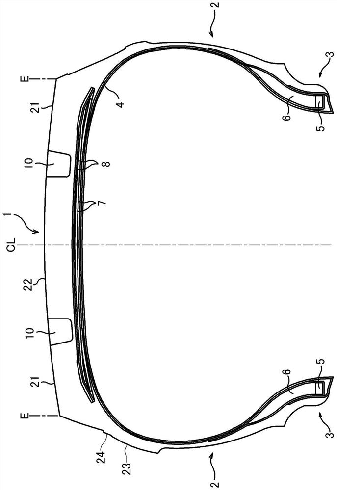
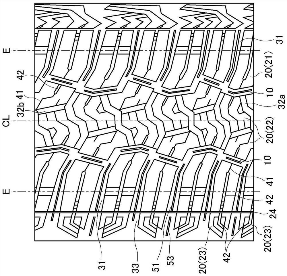
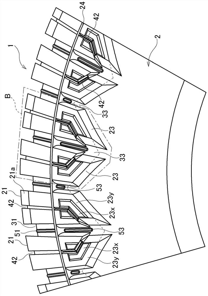
[0047] The tire size is LT265 / 70R17 121Q, with figure 1 The basic configuration is illustrated and ends with figure 2 , 3 The tread pattern is the basic tone, and the positional relationship between the shoulder transverse grooves and the side grooves, the fine grooves formed on the shoulder blocks (indicated as "shoulder fine grooves" in the table) and the fine grooves formed on the sidewall blocks The positional relationship of the grooves (indicated as "sidewall fine grooves" in the table), the contour line along the shoulder transverse groove on the outer side in the tire width direction of the shoulder block (indicated as "transverse groove contour line" in the table) The positional relationship with the contour line of the top surface of the side block along the side groove (indicated in the table as "side groove contour line"), the contour line of the top surface of the side block along the side groove The contour line on the side away from the sidewall groove betwee...


PUM


Abstract

Provided is a pneumatic tire that has improved travel performance and cut resistance on unpaved roads. According to the present invention, block groups B comprise: a pair of adjacent shoulder blocks 21 that sandwich a shoulder lug groove 31; and a pair of adjacent side blocks 23 that sandwich a side groove 33 that is positioned on a line that extends from the shoulder lug groove 31 that is between the pair of shoulder blocks 21. Contour lines L1 of tire-width-direction outside side surfaces of the shoulder blocks 21 and contour lines L3 of top surfaces of the side blocks 23 extend along the same straight lines. Contour lines L3 that, of the contour lines L3 of the top surfaces of the side blocks 23, are on the side that is away from the side groove 33 that is between the pair of side blocks 23 and contour lines L4 of narrow grooves 42 that are formed in the side blocks 23 are formed from straight portions L3a, L4a that extend along the tire radial direction on the shoulder block 21 side and inclined portions L3b, L4b that extend so as to converge toward the side groove 33 that is between the pair of side blocks 23.

Description

technical field [0001] The present invention relates to a pneumatic tire suitable as a tire for running on unpaved roads, and more specifically, to a pneumatic tire having improved running performance and cut resistance on unpaved roads. Background technique [0002] In pneumatic tires intended to run on unpaved roads such as uneven ground, muddy ground, snowy roads, sandy ground, rocky ground, etc., a tread pattern with a large groove area and mainly horizontal grooves and blocks with many edge components is generally used. . In addition, a side block is provided in a side wall region on the outer side in the tire width direction than the shoulder block located on the outermost side in the tire width direction of the tread portion. In such tires, mud, snow, sand, stones, rocks, etc. on the road surface (hereinafter, they are collectively referred to as "mud, etc.") The traction performance is obtained, and the large groove area prevents mud and the like from clogging in t...

Claims


Application Information

Patent Timeline
Patent Type & Authority Applications(China)
IPC IPC(8): B60C13/00B60C11/01B60C11/03B60C11/13
CPCB60C11/01B60C2200/14B60C13/002Y02T10/86B60C13/02B60C2011/1361
Inventor 坂本洋佑
Owner THE YOKOHAMA RUBBER CO LTD
Why Eureka
Try Eureka