Transmitting end, receiving end and system for long-distance wireless charging

A wireless charging and receiving end technology, applied in the transmission system, signal transmission system, electrical components, etc., can solve the problems of high cost and complex hardware structure, and achieve the effect of reducing cost, simplifying hardware structure, and simplifying the transmission path

Pending Publication Date: 2021-04-20
HUAWEI DIGITAL POWER TECH CO LTD
View PDF0 Cites 4 Cited by
  • Summary
  • Abstract
  • Description
  • Claims
  • Application Information

AI Technical Summary

Problems solved by technology

[0004] However, although the above-mentioned transmitting end can realize charging and control

Method used


Image

  • Transmitting end, receiving end and system for long-distance wireless charging
  • Transmitting end, receiving end and system for long-distance wireless charging
  • Transmitting end, receiving end and system for long-distance wireless charging

Examples


Embodiment 1

[0077] The embodiment of the present application provides a transmitter for long-distance wireless charging. The transmitter processor of the transmitter can generate a composite signal according to the power signal and the control signal, and send the composite signal through a transmission path to realize wireless charging and control of the receiver. . The transmitter simplifies the internal hardware structure and reduces the cost of the entire transmitter.

[0078] The embodiments provided by the present application will be described in detail below in conjunction with the accompanying drawings.

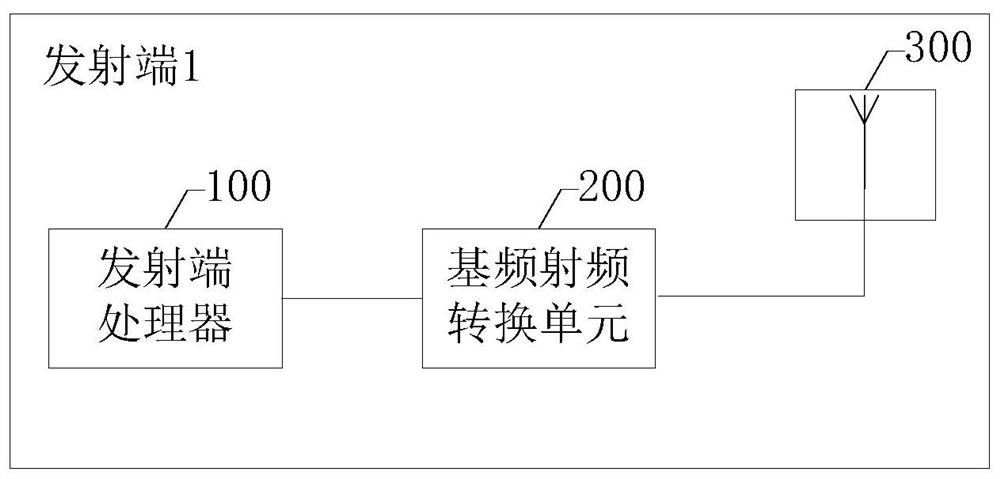
[0079] see image 3 , which is a schematic diagram of a transmitter for long-distance wireless charging provided in this embodiment.

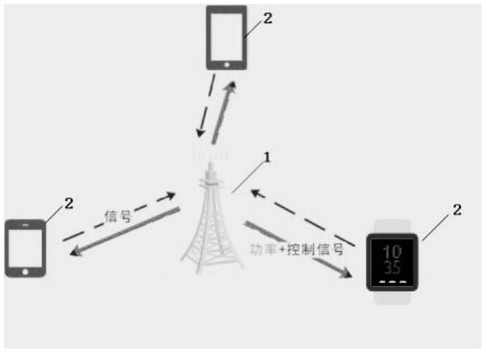
[0080] For the convenience of description, a receiving end is taken as an example for introduction below.

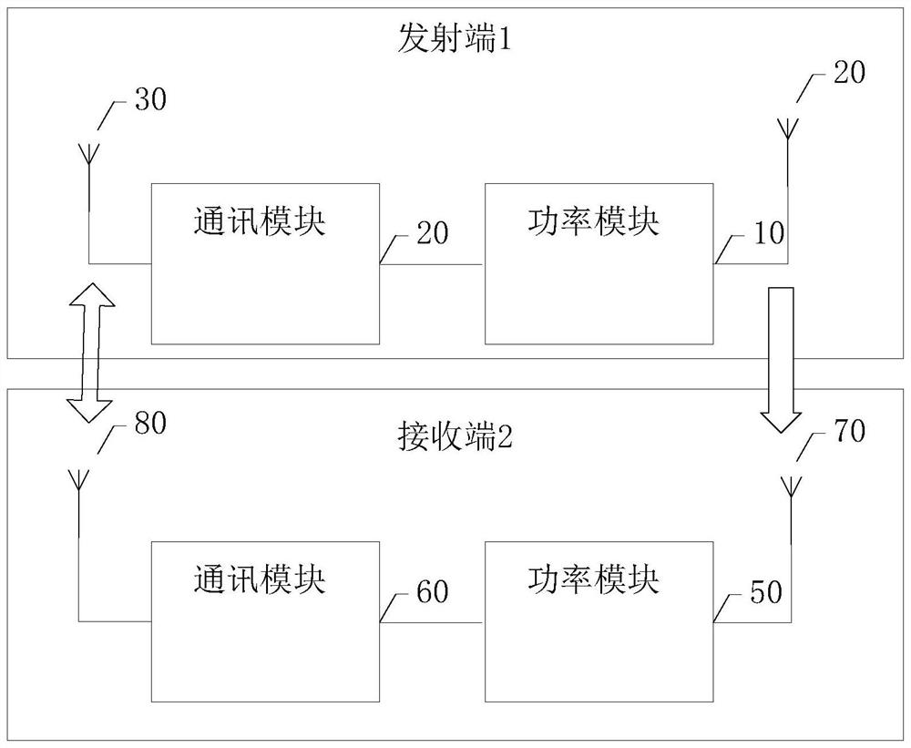
[0081] The transmitter 1 provided in this embodiment is used for wirelessly charging the receiver 2 . The transmitting end 1 includes a...

Embodiment 2

[0105] An embodiment of the present application provides a transmitter for long-distance wireless charging. The transmitter processor of the transmitter can generate a high PAPR waveform according to the feedback signal, and generate a phase modulation signal according to the control signal. The phase modulation signal does not adjust the high PAPR signal waveform. Envelope amplitude, and adjust the phase of the overall high PAPR signal to generate a composite signal, thereby stimulating the receiving end to enter high-efficiency power conversion and improving the output DC power of the receiving end.

[0106] The embodiments provided by the present application will be described in detail below in conjunction with the accompanying drawings.

[0107] see Figure 8 , which is a schematic diagram of another remote wireless charging transmitter provided in this embodiment.

[0108] Wherein, the transmitter processor 100 adopts Figure 4 form, the baseband radio frequency convers...

Embodiment 3

[0138] Because the energy generated by the transmitter will attenuate with the increase of distance. That is, as the distance between the transmitting end and the receiving end increases, the more energy will be consumed on the transmission path, the energy received by the receiving end will decrease, and the transmission power and efficiency will also decrease accordingly. In order to ensure that the receiving end receives energy that meets the requirements of the receiving end, the usage scenarios of the receiving end are divided into fixed scenarios and mobile scenarios for introduction below.

[0139] The fixed scene is a scene in which the position of the receiving end hardly changes during wireless charging. For example, when the receiving end is an IoT device, the range of activities of the IoT device is generally in the factory, warehouse or computer room, and the position of the IoT device hardly changes, that is, the position of the receiving end remains unchanged, w...


PUM


Abstract

The invention discloses a long-distance wireless charging transmitting terminal which is characterized in that the transmitting terminal is used for wirelessly charging a receiving terminal; the transmitting end comprises a transmitting end processor, a fundamental frequency radio frequency conversion unit and a transmitting end antenna. The transmitting end processor is used for generating a composite signal according to the control signal and the power signal and sending the composite signal to the fundamental frequency radio frequency conversion unit; the control signal is used for controlling the working state of the receiving end, and the power signal is used for charging the receiving end; the fundamental frequency radio frequency conversion unit is used for converting the composite signal into a radio frequency signal and sending the radio frequency signal to the transmitting end antenna; and the transmitting end antenna is used for transmitting a radio frequency signal corresponding to the composite signal, and the transmitting end can realize wireless charging and control functions on the receiving end through a composite signal transmission path. According to the transmitting terminal, the internal hardware structure is simplified, and the cost of the whole transmitting terminal is reduced.

Description

technical field [0001] The present application relates to the technical field of wireless charging, and in particular to a transmitter, a receiver and a system for long-distance wireless charging. Background technique [0002] Wireless charging means that the transmitting end provides power to the receiving end in a wireless manner, so as to realize wireless charging to the receiving end. Wireless charging generally uses the principle of electromagnetic induction to achieve wireless energy transfer through coupled electromagnetic fields. [0003] At present, in order to realize long-distance wireless charging, the radio frequency signal emitted by the transmitting end is used as an energy carrier, and the receiving end receives the radio frequency signal and converts it into a DC source to realize the transmission of electric energy. like figure 1 As shown, the long-distance wireless charging system includes a transmitter 1 and a receiver 2 . Wherein, both the transmittin...

Claims


Application Information

Patent Timeline
IPC IPC(8): H02J50/20H02J50/80H04B1/04G08C17/02
CPCH02J50/20H04B1/04H02J50/80G08C17/02
Inventor 潘宁杜志侠蔡兵
Owner HUAWEI DIGITAL POWER TECH CO LTD
Why Eureka
Try Eureka