Riveting machine with hand injury prevention structure for scaffold fastener production

The technology of fasteners and scaffolding is applied in the field of riveting machines with an injury-proof hand structure, which can solve the problems of low safety of riveting machines, and achieve the effects of avoiding manual manual contact, improving the safety of devices, and avoiding contact.

Pending Publication Date: 2021-04-23
安徽华友工程设备有限责任公司
View PDF0 Cites 0 Cited by
  • Summary
  • Abstract
  • Description
  • Claims
  • Application Information

AI Technical Summary

Problems solved by technology

[0004] The object of the present invention is to propose a riveting machine with a hand-injury-proof structure for the production of scaffold fasteners in order to solve the problem of low safety of the existing riveting machine

Method used


Image

  • Riveting machine with hand injury prevention structure for scaffold fastener production
  • Riveting machine with hand injury prevention structure for scaffold fastener production
  • Riveting machine with hand injury prevention structure for scaffold fastener production

Examples


Embodiment 1

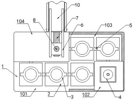
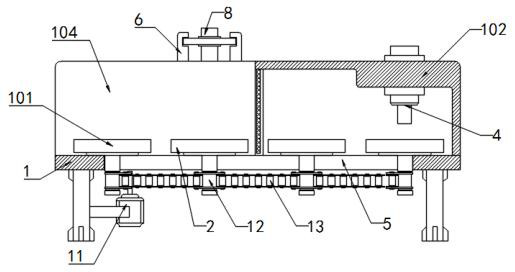
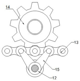
[0032] Example 1, please refer to Figure 1-5 , a riveting machine with an anti-injury structure for the production of scaffold fasteners, including a workbench 1, a riveting machine 4 is arranged on the workbench 1, and the workbench 1 is sequentially provided with a feeding area 101, a press The riveting area 102, the transfer area 103 and the blanking area 104, the workbench 1 is provided with a rectangular slideway 5, and the inside of the slideway 5 is equidistantly provided with a plurality of conveying platforms 2, and the top of the riveting area 102 is fixedly connected with A riveting machine 4, and a protective cover is fixedly connected to the riveting area 102 and the transfer area 103, a hydraulic cylinder 8 is slidably connected to the top of the blanking area 104, and an electromagnet 16 is fixedly connected to the output end of the hydraulic cylinder 8, and the working table 1 is provided with a chain 13 corresponding to the slideway 5, and a gear plate 14 mes...

Embodiment 2

[0033] Example 2, please refer to Figure 1-5 , a riveting machine with an anti-injury structure for the production of scaffold fasteners, including a workbench 1, a riveting machine 4 is arranged on the workbench 1, and the workbench 1 is sequentially provided with a feeding area 101, a press The riveting area 102, the transfer area 103 and the blanking area 104, the workbench 1 is provided with a rectangular slideway 5, and the inner side of the slideway 5 is equidistantly provided with a plurality of conveying platforms 2, and the upper inner side of the conveying platform 2 is provided with a placement slot 3, and the shape of the placement groove 3 is made according to the style of the fastener, there are two groups of rollers 17 in an equidistant annular array on the inner wall of the conveying platform 2, and the two groups of rollers 17 are arranged symmetrically about the horizontal centerline of the conveying platform 2, and The rollers 17 protrude from the conveying...


PUM


Abstract

The invention discloses a riveting machine with a hand injury prevention structure for scaffold fastener production. The riveting machine comprises a workbench and a squeeze riveter; the workbench is sequentially provided with a feeding area, a squeeze riveting area, a transfer area and a discharging area in the anticlockwise direction; a rectangular sliding way is formed in the workbench; a plurality of conveying tables are arranged on the inner side of the sliding way at equal intervals; the squeeze riveter is fixedly connected to the upper portion of the squeeze riveting area; and protective covers are fixedly connected to the squeeze riveting area and the transfer area. According to the riveting machine, feeding, riveting and discharging are arranged in a partitioned mode, influences among all components are reduced, meanwhile, cover plates are arranged on the squeeze riveting area and the discharging area, direct contact between the hands of workers and an internal operation room is avoided, the safety of equipment is improved, and through synchronous operation of a hydraulic cylinder and an electromagnet, fasteners in placing grooves are adsorbed and transferred, so that the discharging operation is completed conveniently, and further contact between the hands and the machine is avoided.

Description

technical field [0001] The invention relates to the technical field of riveting machines, in particular to a riveting machine with an anti-hand injury structure for the production of scaffold fasteners. Background technique [0002] Riveting machine (also known as riveting machine, spin riveting machine, riveting machine, rolling riveting machine, etc.) . It solves the problem that some sheet metal parts cannot be directly placed on the ordinary slope type cast steel machine for pressure riveting after bending. [0003] The existing riveting machine needs to manually support the fasteners during the use process. During the riveting process, a high degree of concentration is required, and the hands need a large grip strength, otherwise the extrusion position deviation will easily occur. , resulting in defective fasteners, and at the same time have certain safety hazards, which constitute a certain threat to the safety of operators. Contents of the invention [0004] The ...

Claims


Application Information

Patent Timeline
Patent Type & Authority Applications(China)
IPC IPC(8): B21J15/42B21J15/32B21J15/38B21J15/14
CPCB21J15/14B21J15/32B21J15/38B21J15/42
Inventor 孙四友
Owner 安徽华友工程设备有限责任公司
Why Eureka
Try Eureka