
Welding tool

A technology for welding tooling and welding parts, applied in welding equipment, auxiliary welding equipment, welding/cutting auxiliary equipment, etc., can solve the problems that the product cannot meet the requirements, the wiring harness cannot be positioned, the welding size and welding direction cannot be controlled, etc.

Pending Publication Date: 2021-04-23
SBT ULTRASONIC TECH CO LTD
View PDF8 Cites 3 Cited by
  • Summary
  • Abstract
  • Description
  • Claims
  • Application Information

AI Technical Summary

Problems solved by technology

[0003] At present, the welding method of the wire harness and the terminal is mainly hand-held welding. This welding method cannot control the size and direction of the welding. Therefore, there is a welding tool in the prior art. The terminal is placed on the workbench, and then The wiring harness is placed on the terminal, and the welding size and welding direction are controlled by clamping the wiring harness and the terminal. However, the workbench of the welding tool in the prior art can only position the terminal, but cannot position the wiring harness. When wiring harnesses, it may cause misalignment between the wiring harness and the terminals, resulting in products that cannot meet the requirements after welding

Method used


Image

  • Welding tool
  • Welding tool
  • Welding tool

Examples


Embodiment Construction

[0046] The present invention will be further described in detail below in conjunction with the accompanying drawings and embodiments. It should be understood that the specific embodiments described here are only used to explain the present invention, but not to limit the present invention. In addition, it should be noted that, for the convenience of description, only some structures related to the present invention are shown in the drawings but not all structures.

[0047] In the description of the present invention, unless otherwise clearly specified and limited, the terms "connected", "connected" and "fixed" should be understood in a broad sense, for example, it can be a fixed connection, a detachable connection, or an integrated ; It can be a mechanical connection or an electrical connection; it can be a direct connection or an indirect connection through an intermediary, and it can be the internal communication of two components or the interaction relationship between two ...


PUM


Abstract

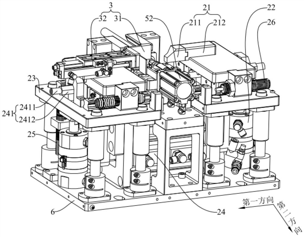
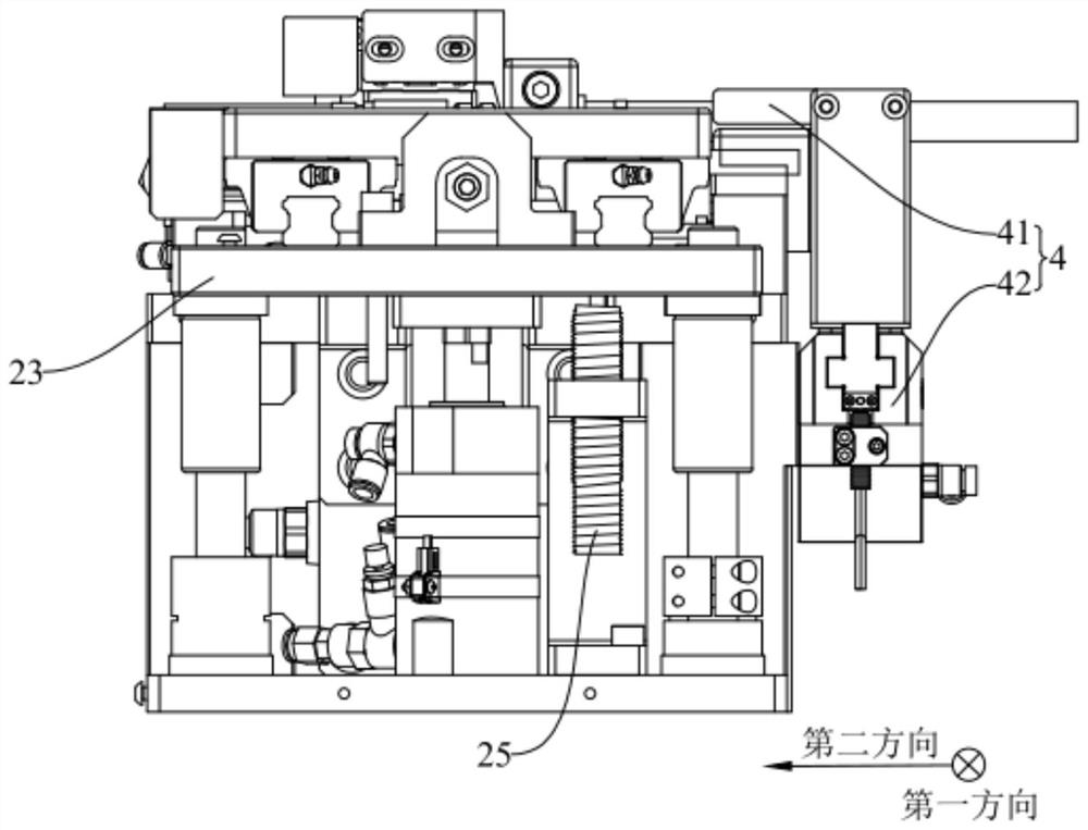
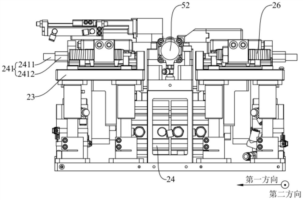
The invention belongs to the technical field of welding, and discloses a welding tool. The welding tool comprises a carrying table, a first positioning mechanism, a second positioning mechanism and a clamping mechanism; the carrying table is provided with a first profiling groove used for carrying a terminal; and the first positioning mechanism can move towards the carrying table so as to abut against and fix the terminal to the carrying table. The second positioning mechanism and the first positioning mechanism can form a second profiling groove in an enclosing mode, and the second profiling groove is used for limiting the carrying position of wire harness so that the to-be-welded portion of the terminal placed in the first profiling groove can be attached to the to-be-welded portion of the wire harness placed in the second profiling groove; the clamping mechanism is configured to fix the wire harness. The first positioning mechanism and the second positioning mechanism are arranged, the terminal and the wire harness are placed in sequence, the first positioning mechanism forms the carrying position of the wire harness with the second positioning mechanism while fixing the terminal so as to position the terminal and the wire harness at the same time, and dislocation between the wire harness and the terminal during wire harness placement is prevented.

Description

technical field [0001] The invention relates to the field of welding technology, in particular to a welding tool. Background technique [0002] The wiring harness and its terminals are the wiring parts that connect various electrical equipment in the circuit, and are widely used in the automotive industry, especially electric vehicles. With the development of the automotive industry, the demand for automotive wiring harnesses and terminals is also increasing. [0003] At present, the welding method of the wire harness and the terminal is mainly hand-held welding. This welding method cannot control the size and direction of the welding. Therefore, there is a welding tool in the prior art. The terminal is placed on the workbench, and then The wiring harness is placed on the terminal, and the welding size and welding direction are controlled by clamping the wiring harness and the terminal. However, the workbench of the welding tool in the prior art can only position the termin...

Claims


Application Information

Patent Timeline
IPC IPC(8): B23K37/04H01R43/02
CPCB23K37/04B23K37/0443H01R43/02
Inventor 周宏建孙松
Owner SBT ULTRASONIC TECH CO LTD
Learn More