Rapid cooling and quenching device for chain production

A rapid cooling and quenching device technology, applied in the direction of quenching devices, furnace types, furnaces, etc., can solve the problems of multiple operations, low quenching quality, and low quenching efficiency

Active Publication Date: 2021-04-23
杭州源景链传动有限公司
View PDF10 Cites 1 Cited by
  • Summary
  • Abstract
  • Description
  • Claims
  • Application Information

AI Technical Summary

Problems solved by technology

[0005] In order to overcome the shortcomings of traditional quenching methods such as many operations, low quenching efficiency and low quenching quality, the technical problem to be solved is: to provide a rapid cooling quenching for chain production with simple operation, high quenching efficiency and improved quenching quality device

Method used


Image

  • Rapid cooling and quenching device for chain production
  • Rapid cooling and quenching device for chain production
  • Rapid cooling and quenching device for chain production

Examples


Embodiment 1

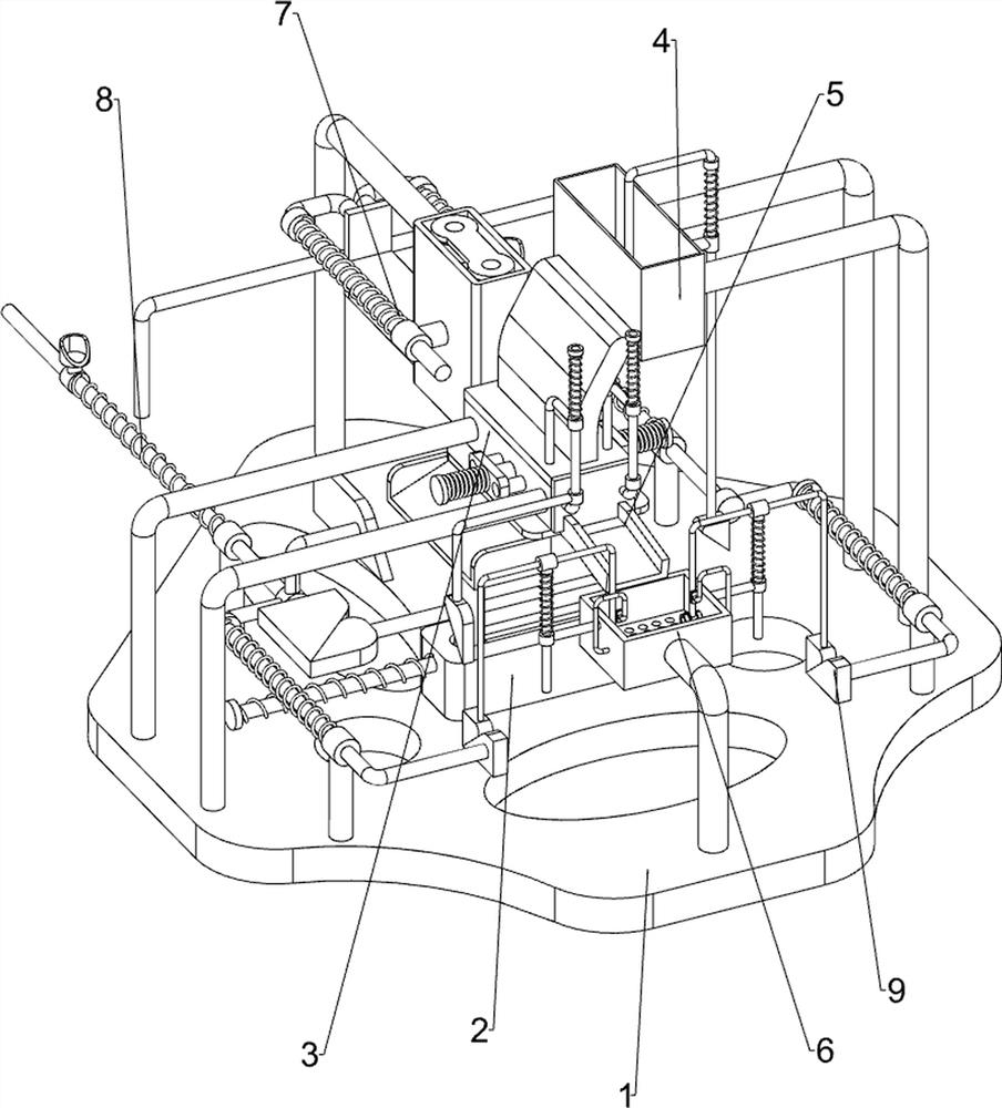
[0082] A rapid cooling and quenching device for chain production, such as figure 1 As shown, it includes a base 1, a sliding burning mechanism 2 and a bearing clamping mechanism 3. The sliding burning mechanism 2 is arranged in the upper middle of the base 1, and the bearing clamping mechanism 3 is arranged on the right side of the base 1.

[0083] When people want to quench the chain, they can use this kind of rapid cooling and quenching device for chain production. First, the user ignites the fire in the sliding burning mechanism 2, and then puts the chain into the load clamping mechanism 3 , the chain is quenched through the sliding burning mechanism 2 to realize the quenching effect of the chain. After the chain quenching is completed, the sliding burning mechanism 2 is extinguished.

Embodiment 2

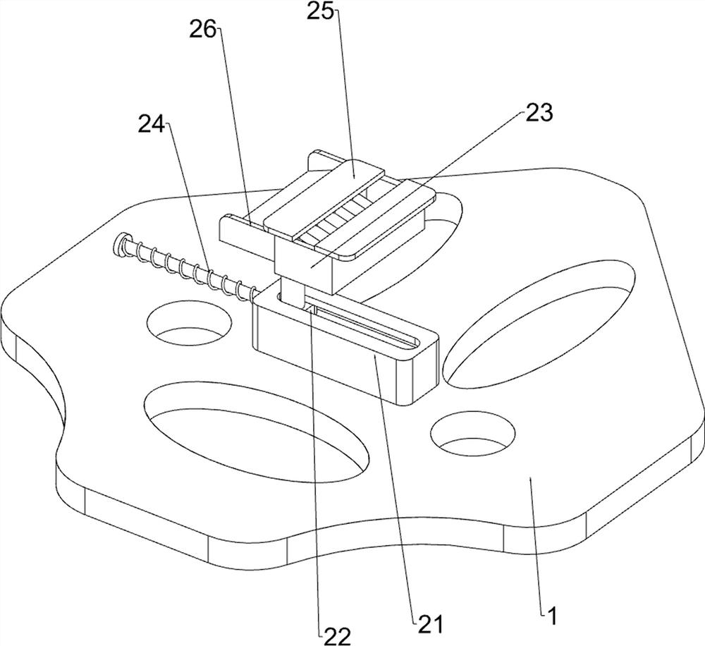
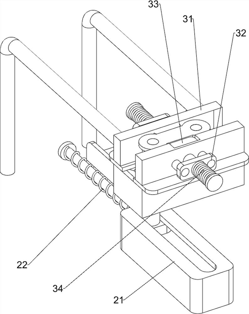
[0085] On the basis of Example 1, such as figure 2 with image 3 As shown, the sliding burning material mechanism 2 includes a support frame 21 with a slide rail, a fixed slider 22, a stove 23, a first spring 24, a placement plate 25 and a water ski 26, and the upper middle part of the base 1 is provided with a slide rail. The support frame 21 is equipped with a sliding rail in the support frame 21, and a fixed slider 22 is arranged on the fixed slider 22. The first spring 24 is wound on the fixed slider 22. The left end of the first spring 24 is connected with the support frame 21 with a slide rail. The right end is connected with fixed slide block 22, and fixed slide block 22 tops are provided with water-skiing board 26, and water-skiing board 26 left walls are provided with burning stove 23, and burning stove 23 tops are provided with two placement plates 25.

[0086] The user puts the chain in the placement plate 25, puts the fuel into the burner 23, ignites it, and then...

Embodiment 3

[0090] On the basis of Example 2, such as Figure 4-Figure 10 As shown, also includes watering mechanism 4, and the left side on base 1 is provided with watering mechanism 4, and watering mechanism 4 includes water discharge frame 41, outlet pipe 42, first sliding sleeve 43, sliding switch plate 44 and the third Spring 45, the left side on the base 1 is provided with a water discharge frame 41, the water discharge frame 41 right wall is provided with a water outlet pipe 42, the water outlet pipe 42 is connected with the fixed frame 31, and the water discharge frame 41 left wall middle part is provided with the first sliding sleeve 43, the first The slide switch plate 44 is slidably arranged on the sliding sleeve 43, the slide switch plate 44 is connected with the base 1, the third spring 45 is wound on the slide switch plate 44, the top of the third spring 45 is connected with the slide switch plate 44, and the third spring The bottom end of 45 is connected with the first slid...


PUM


Abstract

The invention relates to a quenching device, in particular to a rapid cooling and quenching device for chain production. The rapid cooling and quenching device for chain production is easy and convenient to operate, high in quenching efficiency and capable of improving the quenching quality. The rapid cooling and quenching device for chain production comprises a base, wherein a sliding type material burning mechanism is arranged in the middle of the base; and a bearing clamping mechanism which is arranged on the right side of the base. Fuel is put into a burning furnace and ignited, then a user can push a fixed sliding block leftwards, a first spring is compressed, and therefore the burning furnace is driven to move leftwards; and through opposite movement of clamping blocks, a chain in a fixing frame is clamped, and the clamping effect is achieved.

Description

technical field [0001] The invention relates to a quenching device, in particular to a rapid cooling and quenching device for chain production. Background technique [0002] People usually call the solid solution treatment of aluminum alloy, titanium alloy, tempered glass and other materials or the heat treatment process with rapid cooling process as quenching. The traditional chain quenching method is to put the chain into the furnace for heating by workers. After a certain level, the chain is taken out, and the chain is cooled to realize quenching and cooling. During this process, there are many operations, high indoor temperature, and low quenching efficiency. [0003] Patent application CN208071746U, the publication date is 20181109, discloses a metal chain quenching device, including a feeding platform, a heating furnace, a water distribution pipe, a nozzle, a cooling tank and salvage parts, etc., by putting the chain into the feeding platform, heating The furnace heat...

Claims


Application Information

Patent Timeline
Patent Type & Authority Applications(China)
IPC IPC(8): C21D9/00C21D1/63C21D1/52
CPCC21D9/0087C21D9/0025C21D9/0018C21D1/63C21D1/52Y02P10/20
Inventor 杨阿烂
Owner 杭州源景链传动有限公司
Why Eureka
Try Eureka