Waste aluminum treatment equipment

A technology for processing equipment and equipment racks, applied in the direction of improving process efficiency, etc., can solve the problems of difficult design collection and processing, low operation efficiency, etc., and achieve the effects of low energy consumption, high pressing efficiency, and enlarged collection effect

Inactive Publication Date: 2021-04-23
大冶市兴进铝业有限公司
View PDF5 Cites 0 Cited by
  • Summary
  • Abstract
  • Description
  • Claims
  • Application Information

AI Technical Summary

Problems solved by technology

However, this patent has great practical defects. The cutting process of waste aluminum itself needs to supply a huge amount of power energy, and the operation efficiency is low, so it is difficult to effectively design, collect and process

Method used


Image

  • Waste aluminum treatment equipment
  • Waste aluminum treatment equipment
  • Waste aluminum treatment equipment

Examples


Embodiment 1

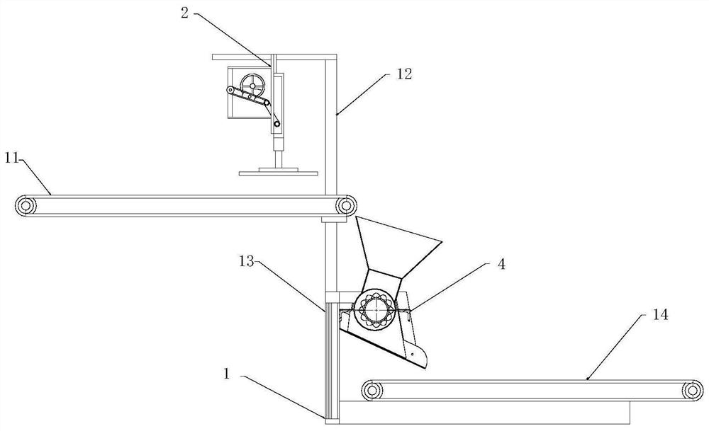
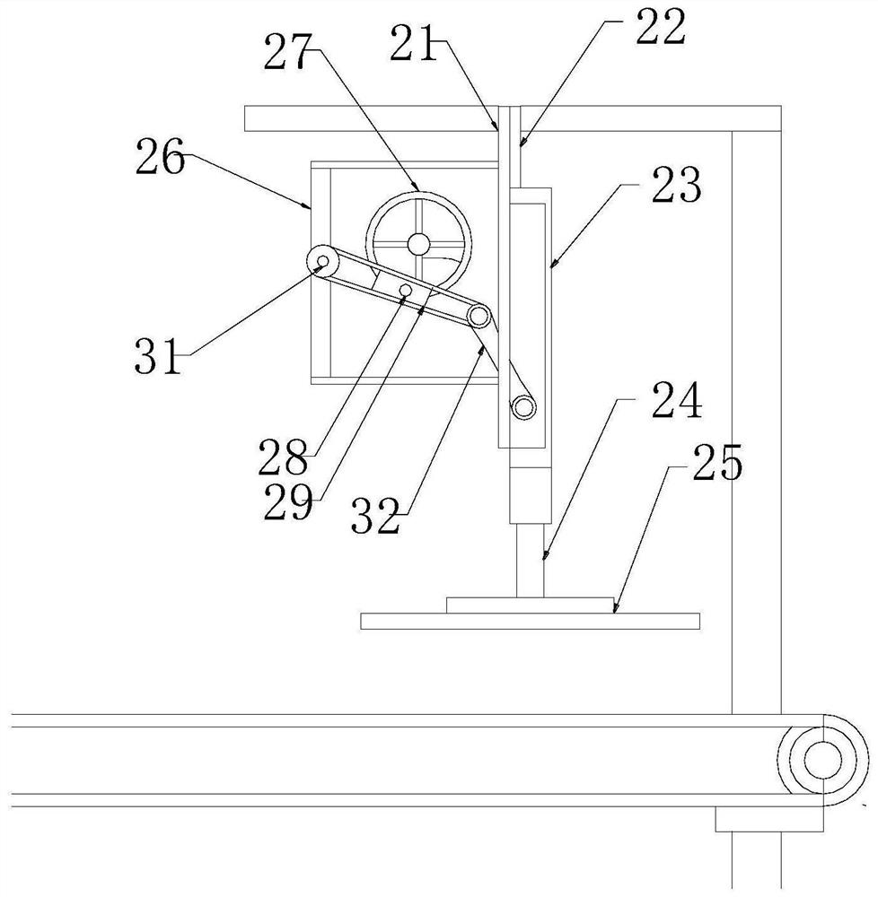
[0024] see Figure 1~3 , a kind of scrap aluminum treatment equipment, comprises frame 1, and described frame 1 is provided with feeding conveyer belt 11 and discharging conveying belt 14, and between described feeding conveying belt 11 and discharging conveying belt 14 is respectively arranged There are an upper equipment rack 12 and a lower equipment rack 13, the upper equipment rack 12 is provided with a primary pressing device 2, and the primary pressing device 2 is provided with a vertical frame 21, the vertical frame 21 is provided with a vertical rail 22, a movable slider 23 is installed on the vertical rail 22, a straight rod 24 is installed on the bottom end of the movable slider 23, and an extrusion plate 25, the extruding plate 25 is located directly above the belt surface of the feeding conveyor belt 11, a transmission frame 26 is arranged on the side of the vertical frame 21, and a transmission disc 27 is installed on the transmission frame 26, and the The disk s...

Embodiment 2

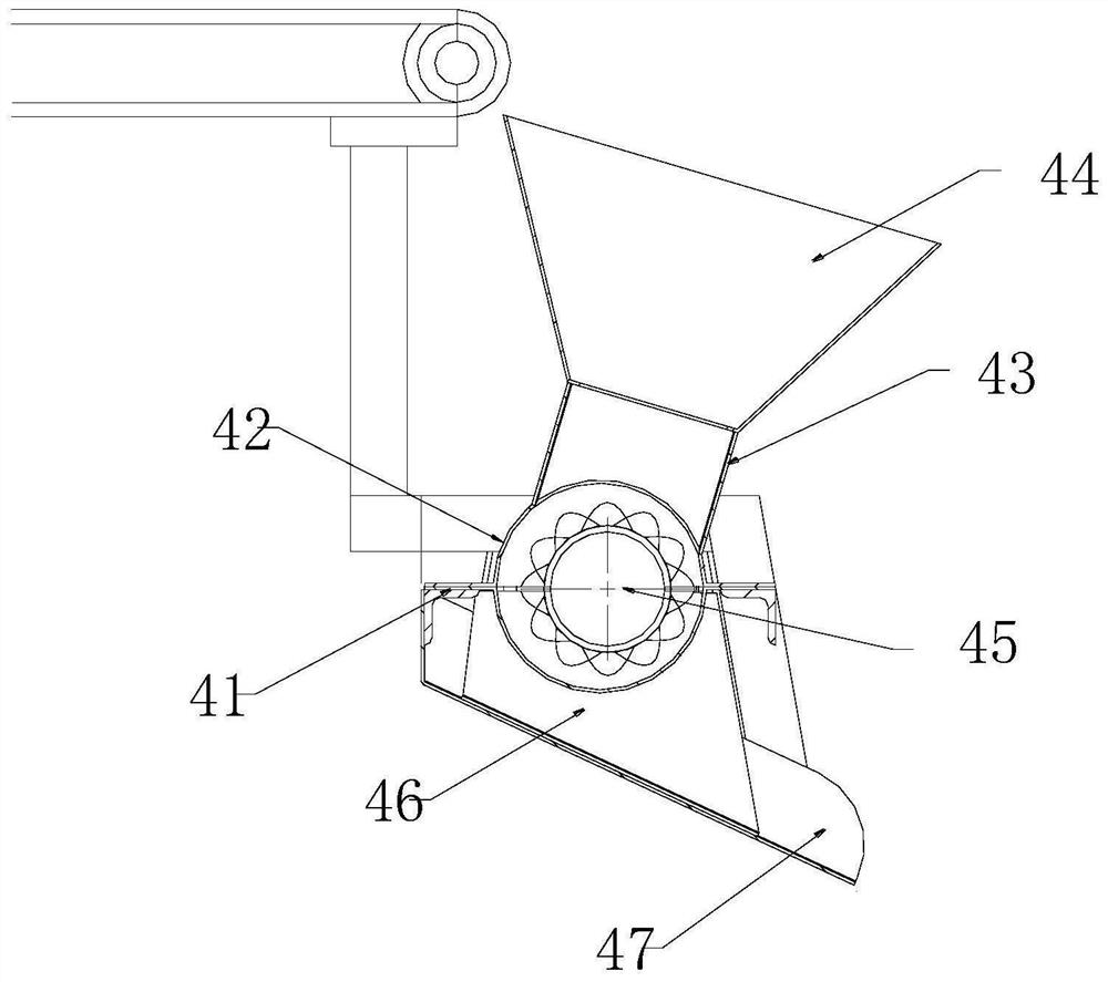
[0028] see image 3 and Figure 4 , this embodiment serves as a further optimization of the first embodiment, on the basis of which, the main body of the extrusion roller 45 is a roller 48, and several extrusion ribs 49 are provided on the sides of the roller 48 in a staggered manner. The installation position of the extrusion roller 45 deviates from the centerline of the extrusion barrel 42, so that one side of the extrusion roller 45 fits the inner wall of the extrusion barrel 42, and the other side of the extrusion roller 45 is in contact with the extrusion material. There is a gap in the inner wall of the barrel 42 . In the present application, there is a gap between the extruding roller 45 and one side of the extruding barrel 42, thereby avoiding the problem of material slipping from both sides and ensuring the adequacy of extruding.


PUM


Abstract

The invention relates to the technical field of aluminum material recovery, in particular to waste aluminum treatment equipment. The waste aluminum treatment equipment comprises a rack, a feeding conveying belt and a discharging conveying belt are arranged on the rack, an upper equipment frame and a lower equipment frame are arranged between the feeding conveying belt and the discharging conveying belt separately, and a first-stage pressing device is arranged on the upper equipment frame. A vertical frame is arranged on the first-stage pressing device, a vertical rail is arranged on the vertical frame, a movable sliding block is installed on the vertical rail, a straight rod is installed at the bottom end of the movable sliding block, an extrusion plate is installed at the bottom end of the straight rod, the extrusion plate is located over the belt surface of the feeding conveying belt, and a second-stage pressing device is arranged on the lower equipment frame. A supporting frame is arranged on the second-stage pressing device, an extrusion charging barrel is installed on the supporting frame, and an extrusion roller is installed in the extrusion charging barrel. According to the waste aluminum treatment equipment, a plane press-fit mode and a roller press-fit mode are adopted, multi-stage press-fit treatment is carried out on an aluminum material, the aluminum material is folded and extruded, and the subsequent space for collecting waste aluminum is reduced.

Description

technical field [0001] The invention relates to the technical field of recycling aluminum materials, in particular to waste aluminum processing equipment. Background technique [0002] Recycling equipment is a device that recycles waste in production or life, so that waste can be reused, which plays a great role in environmental protection and makes the rational use of resources. After years of development, the efficiency of recycling equipment has been greatly improved, but there are still some problems. Traditional recycling equipment cannot cut and shrink waste aluminum, which takes up more space and is inconvenient to process. It is troublesome for staff to move later, which reduces work efficiency and has a certain impact on people's use process. [0003] Chinese patent (authorized announcement number: CN208083589U) discloses a waste aluminum recycling processing equipment, which can cut according to the different sizes and thicknesses of waste aluminum by using a shri...

Claims


Application Information

Patent Timeline
Patent Type & Authority Applications(China)
IPC IPC(8): C22B21/00C22B7/00
CPCC22B21/0069C22B7/005Y02P10/20
Inventor 陈刚
Owner 大冶市兴进铝业有限公司
Why Eureka
Try Eureka