Civil rope catching gun

A rope-catching gun, civilian-use technology, applied in the field of civilian rope-catching guns, can solve problems such as single application, ammunition failure, and affecting the use of rope-catching guns, and achieve the effects of wide application range, simple use, and convenient carrying

Pending Publication Date: 2021-04-23
TIANJIN ZHONGHUAN FUSHI INTELLIGENT EQUIP
View PDF0 Cites 4 Cited by
  • Summary
  • Abstract
  • Description
  • Claims
  • Application Information

AI Technical Summary

Problems solved by technology

But the more rope catcher that uses at present is to adopt the form of the rope catch gun, and the gas expansion after the ammunition explosion is used to launch the anchor hook. As for affecting the use of the rope gun
Moreover, the application of the currently known rope catching guns is relatively single, and is only used for launching ropes.

Method used


Image

  • Civil rope catching gun
  • Civil rope catching gun
  • Civil rope catching gun

Examples


Embodiment 1

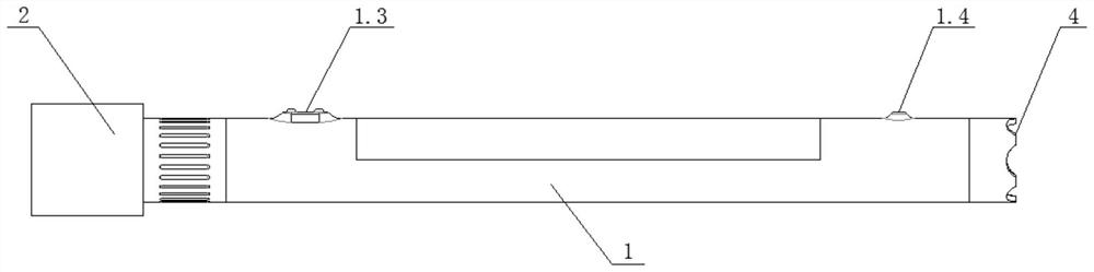
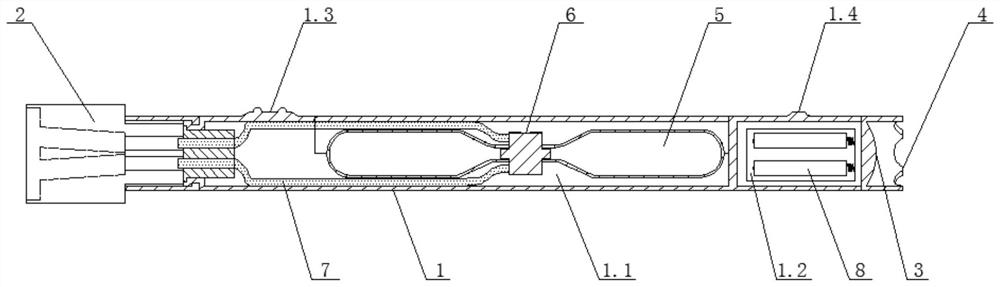
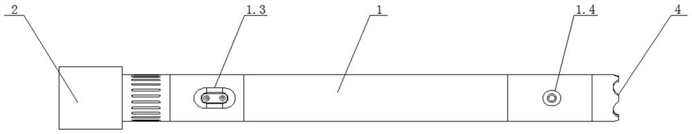
[0031] Embodiment 1: The clip 2 of the rope-catching gun is fixedly connected to the main body 1 of the rope-catching gun through the clip fastening device 2.2, and the clip fastening device 2.2 is connected to the main body 1 of the rope-catching gun through threads , the strong light 3 is fixed on the right end face of the main body 1 of the rope catching gun through threads, the attack head 4 is in the shape of a cylindrical ring, and the left end face of the attack head 4 is fixed on the strong light 3, the attack head 4 and the shell on the high light 3 are integrally structured. The gas bottle 5 , the solenoid valve 6 and the gas pipe 7 are clamped in the inner cavity A1.1, and the battery 8 is clamped in the inner cavity B1.2. The bottlenecks of the two gas cylinders 5 are all connected to the electromagnetic valve 6, and one end of the two air pipes 7 communicates with the two air outlets of the electromagnetic valve 6, and the other ends of the two air pipes 7 pass th...

Embodiment 2

[0032] Embodiment 2: Before use, put the anchor hook and the rope into the anchor hook placement bin 2.1.1 and the rope placement bin 2.1.2 respectively, and then press the solenoid valve push switch 1.3, so that the The solenoid valve 6 is opened, so that the gas in the gas cylinder 5 reaches the air pipe 7 through the battery valve 6, and then reaches the anchor hook placement warehouse 2.1.1 through the air pipe 7, and the anchor hook placement warehouse 2.1. The anchor hook in 1 is subjected to the impact of gas, and will be launched with the rope in the rope placement bin 2.1.2.

[0033]When needing to use illumination in the dark, only need press described strong light push switch 1.4, described strong light 3 just can be used as illumination. When running into danger, when the climber encounters a wild animal, the attacking head 4 can be used as a weapon.


PUM


Abstract

The invention discloses a civil rope catching gun. The civil rope catching gun comprises a rope catching gun body, a rope catching gun clip, an accent light and an attack head. The rope catching gun clip is located at the left end of the rope catching gun body, the accent light and the attack head are located at the right end of the rope catching gun body, and the rope catching gun clip comprises an anchor hook placing device and a clip fastening device. The rope catching gun clip is fixedly connected with the rope catching gun main body through the clip fastening device, the rope catching gun main body is provided with an inner cavity A, an inner cavity B, an electromagnetic valve pressing switch and an accent light pressing switch, a gas cylinder, an electromagnetic valve and a gas pipe are placed in the inner cavity A, a battery is placed in the inner cavity B, the gas cylinder communicates with the rope catching gun clip through the electromagnetic valve and the gas pipe, the accent light is fixed to the right end face of the rope catching gun body, and the attack head is fixed to the accent light. The civil rope catching gun is convenient to carry, easy to use, capable of being used for illumination and explosion prevention and wide in application range.

Description

technical field [0001] The invention relates to the technical field of rope-throwing bombs, in particular to a civilian rope-catching gun. Background technique [0002] Rope catcher is a kind of safety protection device, which is widely used in rescue, climbing and dangerous work. But the more rope catcher that uses at present is to adopt the form of the rope catch gun, and the gas expansion after the ammunition explosion is used to launch the anchor hook. As for affecting the use of the rope gun. Moreover, the application of the currently known rope catching guns is relatively single, and is only applied to launching ropes. Contents of the invention [0003] In view of the above-mentioned defects or deficiencies in the prior art, it is desired to provide a civilian rope catching gun. [0004] According to the technical solution provided by the embodiment of the present application, a civilian rope-catching gun includes a rope-catching gun main body, a rope-catching gun...

Claims


Application Information

Patent Timeline
Patent Type & Authority Applications(China)
IPC IPC(8): F42B12/68
CPCF42B12/68
Inventor 尉丽玲陈卓于文垒刘学睿
Owner TIANJIN ZHONGHUAN FUSHI INTELLIGENT EQUIP
Why Eureka
Try Eureka