Capsule robot for digestive department

A technology of capsule robot and department, applied in the fields of application, medical science, endoscopy, etc., it can solve the problems such as difficult discharge of patients, failure to capture in place, falling speed block, etc., to achieve comprehensive position shooting, improve impact effect, and reduce falling speed Effect

Inactive Publication Date: 2021-04-27
谢美玲
View PDF0 Cites 0 Cited by
  • Summary
  • Abstract
  • Description
  • Claims
  • Application Information

AI Technical Summary

Problems solved by technology

[0004] The main purpose of the present invention is to overcome the deficiencies of the prior art, and provide a capsule robot for digestive departments to solve the problem that the capsule micro-robot is a hard block structure,

Method used


Image

  • Capsule robot for digestive department
  • Capsule robot for digestive department
  • Capsule robot for digestive department

Examples


Example Embodiment

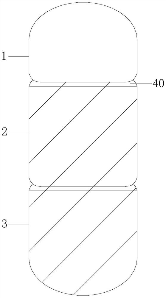
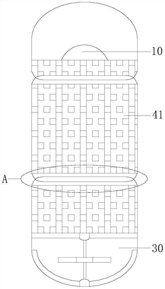
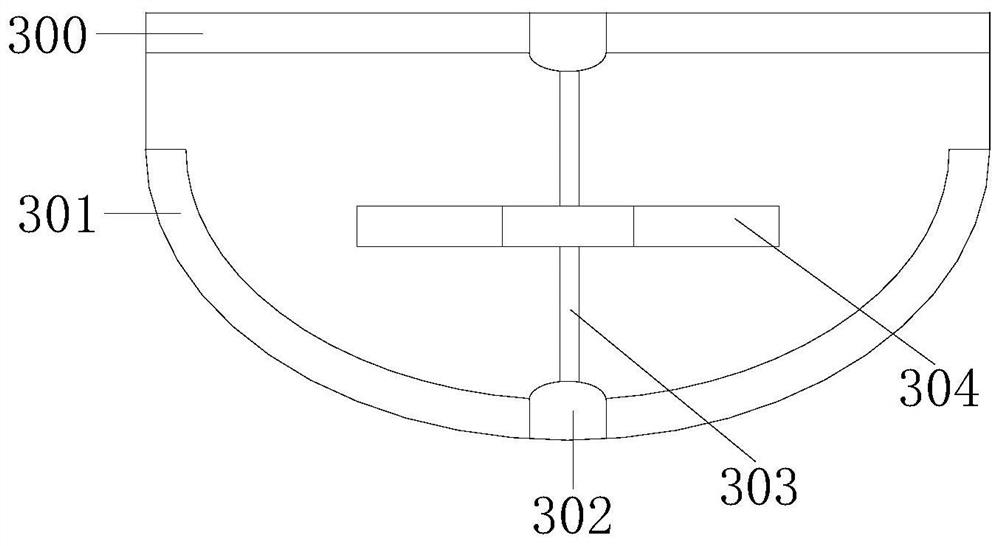
[0026] Example 1 see Figure 1-6 , the present invention provides a capsule robot technical solution for digestive departments: its structure includes an upper cover 1, a middle cover 2, and a bottom cover 3, and the middle cover 2 is threadedly connected with the upper cover 1 and the bottom cover 3, and the upper cover 1, the middle cover 2, and the bottom cover 3 are respectively equipped with a lip 40, and the upper cover 1, the middle cover 2, and the bottom cover 3 are equipped with a power supply 41, and the power supply 41 is connected with a camera 10, and the camera 10 Located at the upper cover 1, the bottom cover 3 is equipped with a magnetic top device 30, and the magnetic top device 30 includes an upper backing plate 300, an arc backing plate 301, a tape rope seat 302, a suspension rope 303, and a magnetic suspension structure 304 , the sling 303 plays an auxiliary role in fixing the magnetic suspension structure 304, the upper backing plate 300 and the arc backi...

Example Embodiment

[0028] Example 2 see Figure 7 , 8 , the present invention provides a technical solution for a capsule robot used in digestive departments: in its structure, the mouth 40 is provided with a connecting thread groove 400, and the thread groove 400 is glued to a cover cloth 81, and the cover cloth 81 is provided with a pull cord 80.

[0029] After the detection is completed, the staff intelligently controls the rotation of the middle cover 2, the upper cover 1, and the bottom cover 3. During the rotation, the middle cover 2 rotates clockwise, the upper cover 1, and the bottom cover 3 rotate counterclockwise, and the stay rope 80 is pulled. Realize that the cover cloth 81 is tightened, namely realize the sealing of each opening of the upper cover 1, the middle cover 2, and the bottom cover 3, and also realize the disconnection of the power supply. At the same time, the upper cover 1, the middle cover 2, and the bottom cover 3 are separated, and the equipment After being divided ...


PUM


Abstract

The invention discloses a capsule robot for the digestive department. The capsule robot structurally comprises an upper cover, a middle cover and a bottom cover, wherein the middle cover is in threaded connection with the upper cover and the bottom cover; the upper cover, the middle cover and the bottom cover are each provided with an edge opening; the upper cover, the middle cover and the bottom cover is provided with a power supply; the power supply is connected with a camera; the camera is arranged at the upper cover; the bottom cover is provided with a magnetic jacking device; the magnetic jacking device comprises an upper base plate, an arc base plate, a magnetic tape rope seat, a lifting rope and a magnetic lifting structure; the upper base plate and the arc base plate form a relative structure; the upper base plate, the arc base plate and the magnetic tape rope seat are connected through glue; and the lifting rope penetrates through the magnetic lifting structure. According to the invention, equipment is pushed up by the magnetic jacking device, namely, the falling speed of the equipment is reduced, so that position shooting is more comprehensive and the scanning precision is improved; and the capsule micro-robot is composed of the upper cover, the middle cover and the bottom cover, so that the capsule micro-robot can be discharged out of the body more conveniently after being separated.

Description

technical field [0001] The invention relates to the field of gastroenterology equipment, in particular to a capsule robot for the gastroenterology department. Background technique [0002] Capsule micro-robot is an intelligent micro-tool that can enter the human gastrointestinal tract for medical exploration and treatment. It is a new breakthrough in medical technology for interventional examination and treatment in the body. No difference. The working principle and method of the capsule micro-robot: first electrify the micro-robot, and then send it into the body, the robot slowly traverses the gastrointestinal tract with the gastrointestinal movement of the human body, the micro-camera unit carried in the robot takes images of the cavity, and The radio frequency signal is transmitted to the external receiving device through the miniature wireless transmitting module, and the staff can perform medical image observation, processing and diagnosis and treatment on the receivin...

Claims


Application Information

Patent Timeline
IPC IPC(8): A61B1/04A61B1/273
CPCA61B1/00137A61B1/00158A61B1/041A61B1/273
Inventor 林秀宝
Owner 谢美玲
Why Eureka
Try Eureka