
Eureka
For R&D, Eureka makes reading and utilizing patents & technical documents easy.
Eureka AIR
Designed for self-driven R&D workflows. Generate viable solutions, solve complex R&D challenges, empower your innovation with AI.

Eureka Materials
Designed for material experts only. Revolutionize your material R&D, from search, analyze, to developing new materials.

TechResearch
Generate reliable direction feasibility study reports for your R&D in just a few steps.

TechSeek
Discover and master advanced knowledge NOW. Basics, ideas, possibilities, all at once.

TechMind
As an expert in R&D Theories, TechMind can generates customized viable solutions instantly.

TechRisk
Analyze your overall solution with one click, know your potential R&D risks in advance.

TechMonitor
Get weekly tech updates, stay abreast of the latest tech innovations and key insights.
Tumor excision device for oncology department
A resectator and tumor technology, applied in the field of tumor resectoscopes used in oncology, can solve problems such as damage, affect the progress of surgery, increase the difficulty of doctors' operations, etc., and achieve the effect of ensuring stability
- Summary
- Abstract
- Description
- Claims
- Application Information
AI Technical Summary
Problems solved by technology
Method used
Image

Examples
Embodiment 1
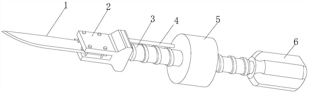
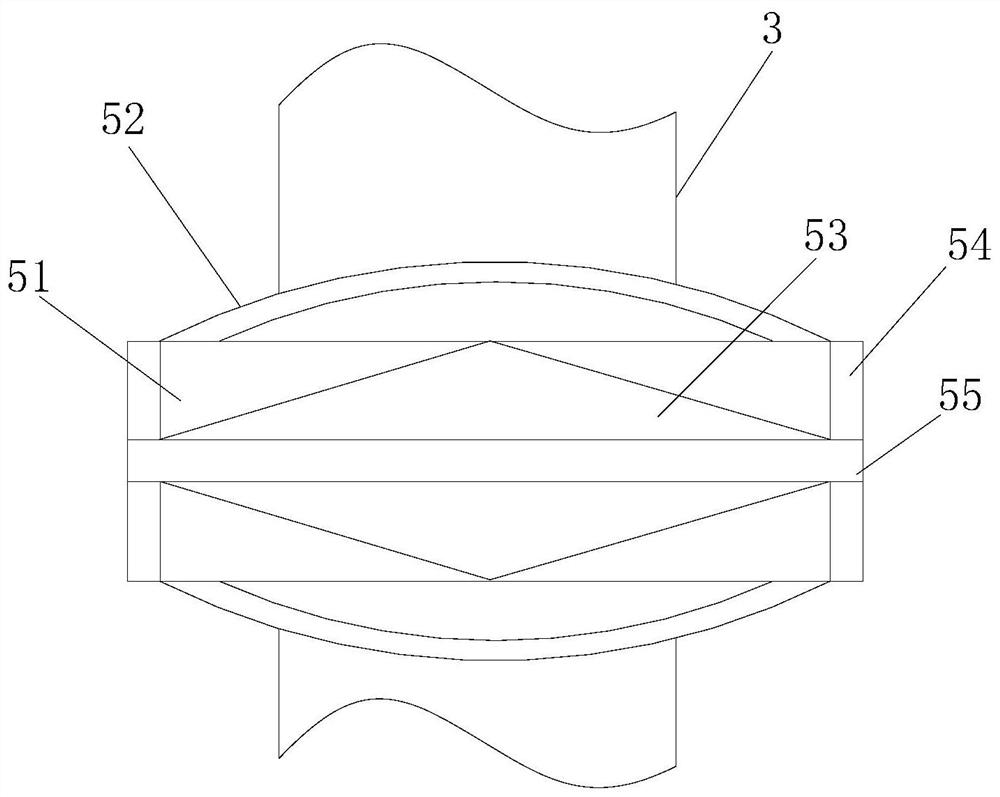
[0027] like Figure 1-Figure 3 As shown, the present invention provides a tumor resectator for oncology, its structure includes a cutting knife 1, a handle 2, a threaded knife rod 3, a limiting rod 4, a sleeve 5, a rotating head 6, and the cutting knife 1 passes through the handle 2 It is fixedly connected with the threaded knife rod 3, the threaded knife rod 3 and the limiting rod 4 are inserted inside the sleeve 5, the sleeve 5 adopts a transition fit mode to cooperate with the rotating head 6, and the sleeve 5 includes a buckle 51. Power booster 52, composite plate 53, cylinder body 54, and partition 55. The outer surface of the buckle 51 is welded and connected with a partition 55. Both sides of the partition 55 are scarfed and connected with composite panels 53. The composite The two sides of the plate 53 are sleeved on the inner wall of the cylinder 54, and the top of the cylinder 54 is equipped with a booster device 52. The booster device 52 indirectly cooperates with t...
Embodiment 2
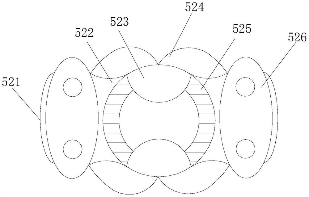
[0029] like Figure 4-Figure 6 As shown, on the basis of Embodiment 1, the present invention combines the mutual cooperation of the following structural components. The entrainment belt 523 includes a buckle bucket 3a1, a rotary plate 3a2, a weight pad 3a3, a spreader plate 3a4, and an insert 3a5. The buckle Bucket 3a1 is a bucket-shaped structure, its open end is movably engaged with plug-in 3a5, and its connecting end is welded with rotating plate 3a2, and a stretching plate 3a4 is indirectly fitted between the rotating plates 3a2, and the weight pad 3a3 is embedded It is connected to the outer surface of the rotating plate 3a2, and the bottom of the expansion plate 3a4 is fixedly connected to the retaining ring 525. The gathering assembly 524 includes a sleeve cavity 4b1, a guide inclined plate 4b2, an adapter 4b3, a limit device 4b4, Leg 4b5, positioning frame 4b6, the socket cavity 4b1 is welded on the inner side of the bottom of the positioning frame 4b6, and the opening...
PUM
 Abstract
Description
Claims
Application Information
 - R&D Engineer
- R&D Manager
- IP Professional
- Industry Leading Data Capabilities
- Powerful AI technology
- Patent DNA Extraction
Browse by: Latest US Patents, China's latest patents, Technical Efficacy Thesaurus, Application Domain, Technology Topic, Popular Technical Reports.
© 2024 PatSnap. All rights reserved.Legal|Privacy policy|Modern Slavery Act Transparency Statement|Sitemap|About US| Contact US: help@patsnap.com