Ultrasonic-assisted tapping device
A tapping device and ultrasonic-assisted technology, applied in the direction of tangential device, tangential feeding device, fluid using vibration, etc., can solve the problems of easily damaged tools, the influence of machining accuracy, and slow processing efficiency, so as to avoid damage and improve Machining accuracy, time reduction effect
- Summary
- Abstract
- Description
- Claims
- Application Information
AI Technical Summary
Problems solved by technology
Method used
Image

Examples
Embodiment
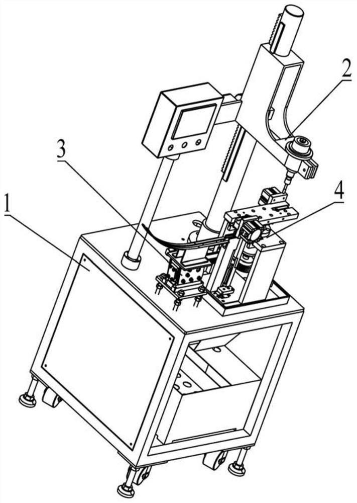
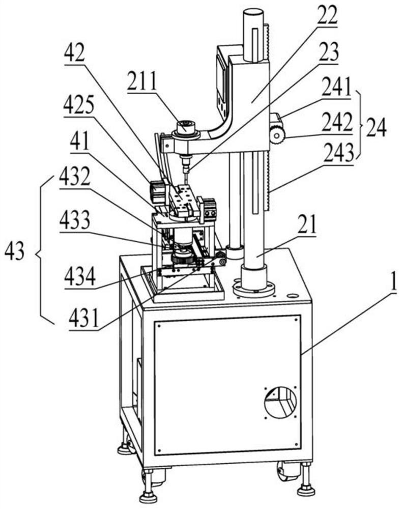
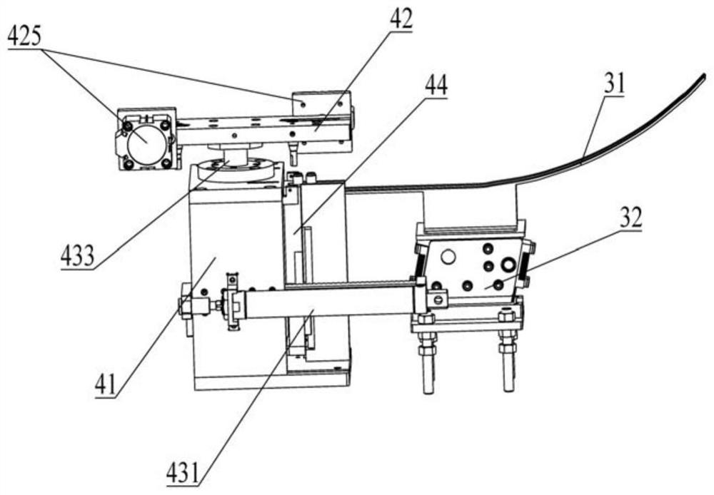
[0028] Such as Figure 1 to Figure 7As shown, it is an embodiment of an ultrasonic-assisted tapping device of the present invention, including a workbench 1 and an ultrasonic tapping mechanism 2, a feeding mechanism 3, and a clamping mechanism 4 that are all arranged on the workbench 1; The material mechanism 4 includes a fixed seat 41, a clamping plate 42 that is rotatably arranged on the fixed base 41, a first drive mechanism 43 that drives the rotation of the clamping plate 42, and a top material plate 44; There is a vertical slide rail 11, and the top material plate 44 is slidably connected with the slide rail 11; a plurality of clamping parts are arranged on the clamping plate 42, and the top material plate 44 is arranged on the clamping part. Below: the feeding mechanism 3 is arranged between the top material plate 44 and the clamping member and connected to the top of the top material plate 44 .
[0029] Of course, a driving device for driving the movement of the eject...
PUM
 Abstract
Description
Claims
Application Information
PatSnap Eureka turns technology decisions into work you can execute. Powered by our Innovation Knowledge Graph, it runs expert workflows across engineering, life sciences, materials and intellectual property. Get your review-ready output in minutes.


