Clamping table with alarm function for machining

A mechanical processing and functional technology, applied in the direction of manufacturing tools, metal processing equipment, metal processing machinery parts, etc., can solve problems such as inability to guarantee processing safety and accuracy, low processing efficiency, time and energy wasted in workpiece disassembly

Pending Publication Date: 2021-04-27
LIAONING UNIVERSITY OF PETROLEUM AND CHEMICAL TECHNOLOGY
View PDF7 Cites 2 Cited by
  • Summary
  • Abstract
  • Description
  • Claims
  • Application Information

AI Technical Summary

Problems solved by technology

[0004] The technical problem to be solved by the present invention is to overcome the existing defects and provide a clamping platform with an alarm function for mechanical processing, so as to solve the problem that the existing clamps proposed in the background technology are usually manually clamped and clamped when used. When the holding is not in place, the alarm cannot be issued, the processing safety and accuracy cannot be guaranteed, and it is a waste of time and energy to disassemble the workpiece many times, which leads to the problem of low processing efficiency

Method used


Image

  • Clamping table with alarm function for machining
  • Clamping table with alarm function for machining
  • Clamping table with alarm function for machining

Examples


Embodiment 1

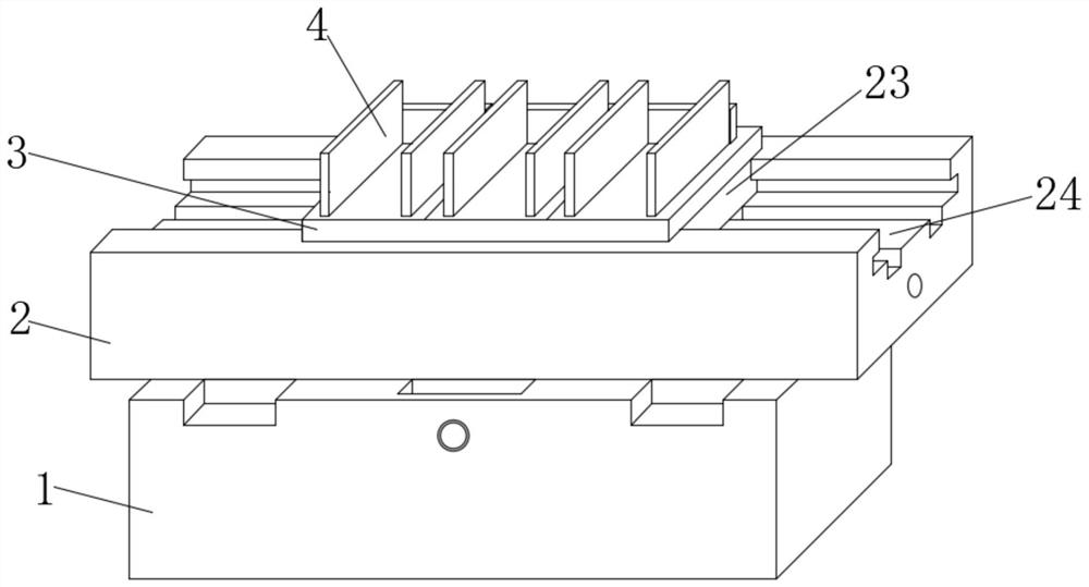
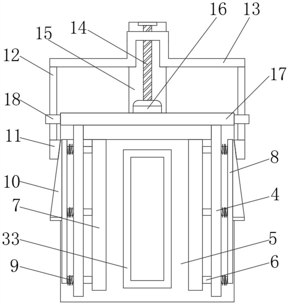
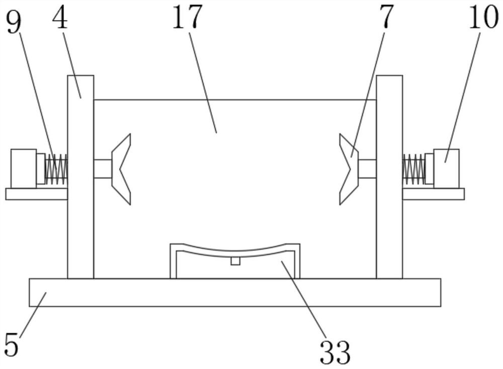
[0033] see Figure 1-8 , the present invention provides a technical solution: a clamping platform with an alarm function for mechanical processing, including a base 1 and a supporting platform 2, the top of the base 1 is slidably connected to the supporting platform 2, and the top of the supporting platform 2 is slidably connected to a clamping plate 3. The top of the clamping plate 3 is evenly provided with a splint group 4. The splint group 4 is located at the top of the base plate 5. The base plate 5 is located at the top of the clamping plate 3. The inner side of the splint set 4 is slidingly connected with a slide bar 6. The slide bar 6 is located in the splint set. One end of the inner side of 4 is fixedly connected with clamp block 7, the other end of slide bar 6 is fixedly connected with connecting plate 8, and the outer side of slide bar 6 is located between connecting plate 8 and splint group 4, and a first spring 9 is arranged, and the opposite outer side of connecti...

Embodiment 2

[0037] see Figure 1-8 , the present invention provides a technical solution: a clamping platform with an alarm function for mechanical processing, including a base 1 and a supporting platform 2, the top of the base 1 is slidably connected to the supporting platform 2, and the top of the supporting platform 2 is slidably connected to a clamping plate 3. The top of the clamping plate 3 is evenly provided with a splint group 4. The splint group 4 is located at the top of the base plate 5. The base plate 5 is located at the top of the clamping plate 3. The inner side of the splint set 4 is slidingly connected with a slide bar 6. The slide bar 6 is located in the splint set. One end of the inner side of 4 is fixedly connected with clamp block 7, the other end of slide bar 6 is fixedly connected with connecting plate 8, and the outer side of slide bar 6 is located between connecting plate 8 and splint group 4, and a first spring 9 is arranged, and the opposite outer side of connecti...


PUM


Abstract

The invention discloses a clamping table with an alarm function for machining. The clamping table comprises a base and a supporting table, wherein the supporting table is slidably connected to the top end of the base. By arranging a motor, the motor drives a screw to rotate, then the screw drives a support at the outer side of the screw to move, when the support gets close to a limiting boss, the two ends of the support push push rods to slide at the inner sides of spacing rings, and then the push rods push pressing blocks to slide at the outer sides of trapezoidal blocks, the trapezoidal blocks and connecting plates push sliding rods to slide at the inner sides of the clamping plate sets, the ends, located at the opposite inner sides of the clamping plate sets, of the sliding rods are fixedly connected to the clamping blocks, then the clamping blocks clamp the two sides of a workpiece, and then the automatic clamping effect is achieved; and by arranging a pressing plate and a proximity switch, when the pressing plate slides to the bottom end, the other end of a supporting rod just reaches the induction distance of the proximity switch, it shows that the pressing plate is extruded in place, at the moment, the motor stops clamping, a machine tool gives a buzzing alarm, and the effect of giving an alarm during clamping is achieved.

Description

technical field [0001] The invention belongs to the technical field of mechanical processing, and in particular relates to a clamping table with an alarm function for mechanical processing. Background technique [0002] Machining refers to the process of changing the shape or performance of a workpiece through a mechanical device; it can be divided into cutting processing and pressure processing according to the difference in processing methods; in the process of mechanical processing, it is often necessary to use a drilling machine to drill holes Processing, usually the main movement of the drill bit is rotation, and the axial movement of the drill bit is the feed movement; the drilling machine has a simple structure and relatively low machining accuracy. It can drill through holes, blind holes, replace special tools, expand, countersink, ream or carry out Tapping and other processing; the workpiece does not move during the processing, let the tool move, align the center of...

Claims


Application Information

Patent Timeline
Patent Type & Authority Applications(China)
IPC IPC(8): B23Q3/06B23Q11/00
CPCB23Q3/06B23Q11/00
Inventor 于新丽王蕤
Owner LIAONING UNIVERSITY OF PETROLEUM AND CHEMICAL TECHNOLOGY
Why Eureka
Try Eureka