Probe system for electromagnetic environment monitoring
An environmental monitoring and electromagnetic technology, applied in the fields of electromagnetic field characteristics, measuring devices, measuring electrical variables, etc., can solve the problem of low accuracy
- Summary
- Abstract
- Description
- Claims
- Application Information
AI Technical Summary
Problems solved by technology
Method used
Image

Examples
Embodiment Construction
[0040] The following is attached Figure 1-7 The application is described in further detail.
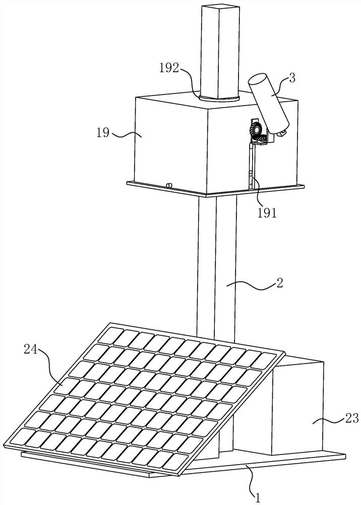
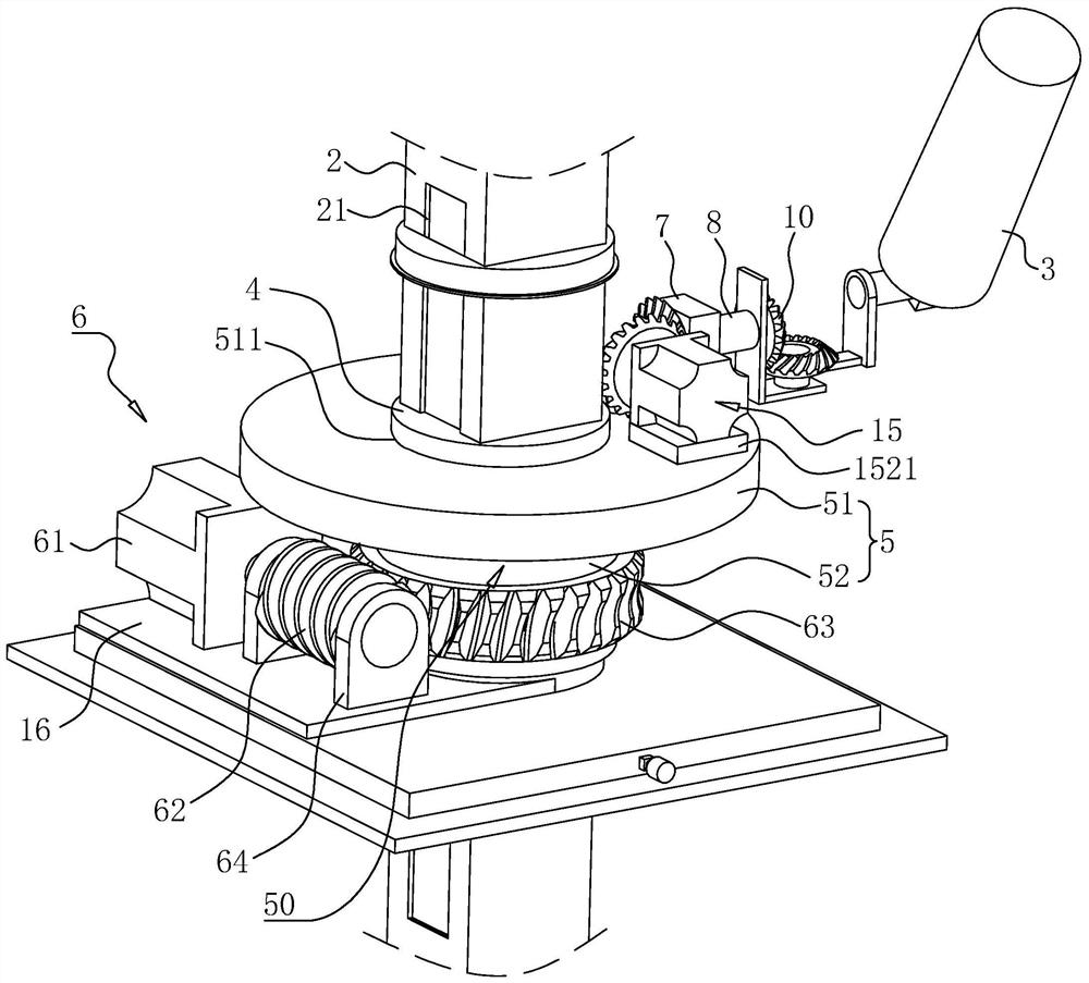
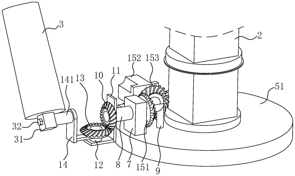
[0041] The embodiment of the present application discloses a probe system for electromagnetic environment monitoring. refer to figure 1 and figure 2 The probe system used for electromagnetic environment monitoring includes a base 1, the top wall at one end of the base 1 is fixedly connected with an organic case 23, and the top wall at the other end of the base 1 is fixedly connected with a solar photovoltaic panel 24, and the solar photovoltaic panel 24 is electrically connected to the chassis 23. connection, the chassis 23 is used to store electric energy so as to supply power to the probe system, the top wall of the base 1 is fixedly connected with the pole 2, the pole 2 is coaxially sleeved and slidably connected with the base 4, and the base 4 deviates from The side wall on one side of the pole 2 is rotatably connected with an adjustment seat 5, on which the monitoring device...
PUM
 Abstract
Description
Claims
Application Information
PatSnap Eureka turns technology decisions into work you can execute. Powered by our Innovation Knowledge Graph, it runs expert workflows across engineering, life sciences, materials and intellectual property. Get your review-ready output in minutes.


