
Wearable equipment

A technology of wearable equipment and equipment, which is applied to antennas, antennas, antenna parts and other directions suitable for movable objects, and can solve the problems of increased complexity of mechanical design and manufacturing, inconvenient replacement of non-replaceable lenses, and damaged lens replaceability and other issues, to achieve the effect of promoting replaceability, small temple size, minimizing complexity and cost

Active Publication Date: 2021-04-27
英特睿达(山东)电子科技有限公司
View PDF10 Cites 1 Cited by
  • Summary
  • Abstract
  • Description
  • Claims
  • Application Information

AI Technical Summary

Problems solved by technology

[0005] But antenna designs feeding integrated mirrors pose challenges that lead to increased mechanical design and manufacturing complexity, compromised mirror replaceability, etc.
To connect the antenna to the RF transmit and receive unit, the traditional way is to use a coaxial cable or transmission line and solder the coaxial cable or transmission line to the lens. inconvenient
Soldering (or any form of electrical contact to the lens-integrated antenna) may also result in reduced contact resistance due to corrosion

Method used


Image

  • Wearable equipment
  • Wearable equipment
  • Wearable equipment

Examples


Embodiment Construction

[0029] Reference will now be made in detail to the exemplary embodiments, examples of which are illustrated in the accompanying drawings. When the following description refers to the accompanying drawings, the same numerals in different drawings refer to the same or similar elements unless otherwise indicated. The implementations described in the following exemplary examples do not represent all implementations consistent with this disclosure. Rather, they are merely examples of apparatuses and methods consistent with aspects of the present disclosure as recited in the appended claims.

[0030] The terminology used in the present disclosure is for the purpose of describing particular embodiments only and is not intended to be limiting of the present disclosure. Unless defined otherwise, all other scientific and technical terms used herein have the same meaning as commonly understood by one of ordinary skill in the art to which this invention belongs. As used in this disclosu...


PUM


Abstract

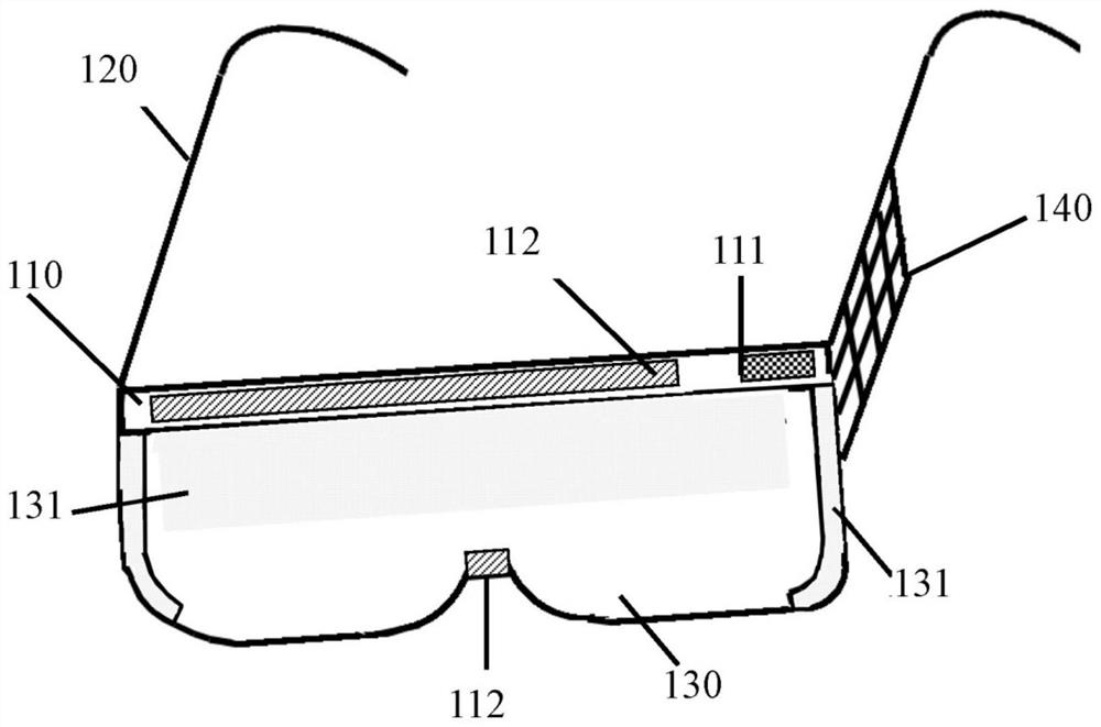
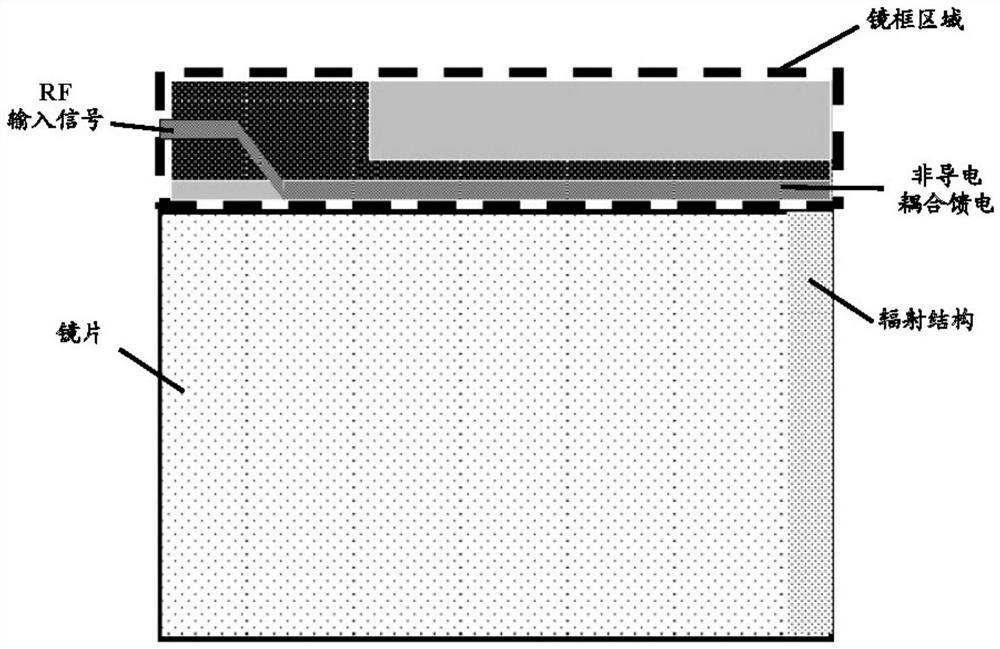
The present disclosure relates to wearable equipment, which comprises: a first component and a second component, wherein an antenna is integrated on the first component, an RF transmitting and receiving unit for receiving and transmitting an antenna signal is arranged on the second component, and is connected to a first coupled feeding element, the first coupled feeding element is embedded in the second component, and the first coupled feeding element in the second component and the antenna are isolated from each other and are parallel or coplanar, so that the antenna is configured to receive a signal from the RF transmitting and receiving unit and transmit the signal to the RF transmitting and receiving unit through electrical coupling with the first coupled feeding element.

Description

technical field [0001] The present disclosure relates to the field of wireless communication applications, in particular to smart glasses with a compact structure. Background technique [0002] Today's wearable devices (such as smart watches, smart glasses, small size and more and more functional designs), the number of radios these devices need to support (Bluetooth, GPS, WiFi, 3G / 4G / LTE, FM) and related Technology antennas are increasing. Typically, the antenna is hidden in a large bezel around the display or in a frame that surrounds a glass lens. Large-area lenses occupy the entire size. [0003] In prior art wearable devices, such as many smart glasses, the antenna is integrated in the PCB housing. The antennas needed for smart glasses are placed in the non-lens frame. However, the area or volume of the frame is too small to meet the requirements of the transmitting power of the antenna. In the technical solution of integrating the antenna of the smart glasses in t...

Claims


Application Information

Patent Timeline
Patent Type & Authority Applications(China)
IPC IPC(8): H01Q1/27H01Q1/50
CPCH01Q1/273H01Q1/50
Inventor 柴玫
Owner 英特睿达(山东)电子科技有限公司
Learn More