
Built-in permanent magnet dismounting device and method of permanent magnet rotor

A technology of permanent magnet rotor and dismantling device, which is applied in the manufacture of stator/rotor body, electromechanical device, transportation and packaging, etc., can solve the problems of unusable permanent magnet, falling angle of permanent magnet, small permanent magnet, etc., and achieves rapid manufacturing and application. , does not occupy the space, the effect of short production cycle

Active Publication Date: 2021-04-27
CRRC YONGJI ELECTRIC CO LTD
View PDF13 Cites 0 Cited by
  • Summary
  • Abstract
  • Description
  • Claims
  • Application Information

AI Technical Summary

Problems solved by technology

[0004] This solution is only suitable for smaller permanent magnet rotors. The permanent magnets are small, and the number in each slot is small. The permanent magnets can be knocked manually, but the efficiency is extremely low, and the removed permanent magnets are basically all corners off. , or damaged, can no longer be used
For medium and large permanent magnet rotors, when the number of permanent magnets in each slot is large, it is impossible to knock the permanent magnets manually, and the entire rotor can only be scrapped.

Method used


Image

  • Built-in permanent magnet dismounting device and method of permanent magnet rotor
  • Built-in permanent magnet dismounting device and method of permanent magnet rotor
  • Built-in permanent magnet dismounting device and method of permanent magnet rotor

Examples


Embodiment Construction

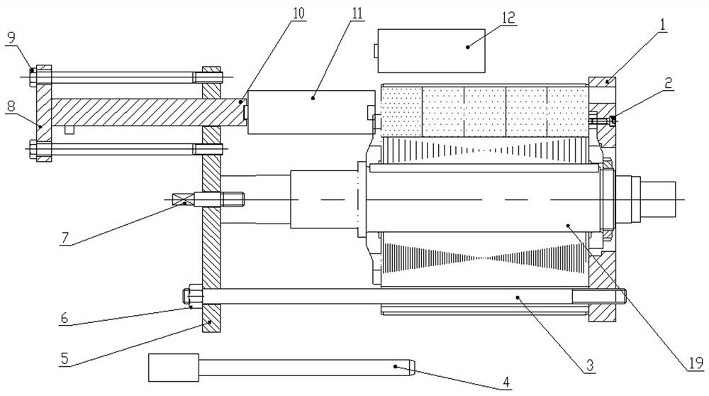
[0025] Such as figure 1 As shown, the present invention is mainly composed of the following 12 parts, including positioning plate 1, screw 2, pull rod 3, positioning column 4, fixing plate 5, nut 6, positioning pin 7, oil cylinder base 8, bolt 9, oil cylinder 10, first Top block 11, second top block 12.

[0026] Part 19 is the rotor assembled with permanent magnets.

[0027] The positioning plate 1 is fixed on the rotor with screws 2. The positioning plate 1 is made of stainless steel plate. The positioning plate 1 has a through hole (rectangular hole) that is a little larger than the permanent magnet groove, so as to ensure that the permanent magnet can be taken out smoothly after being pushed out. , to avoid being directly attracted to other objects after being pushed out, causing damage to the permanent magnet and other injuries.

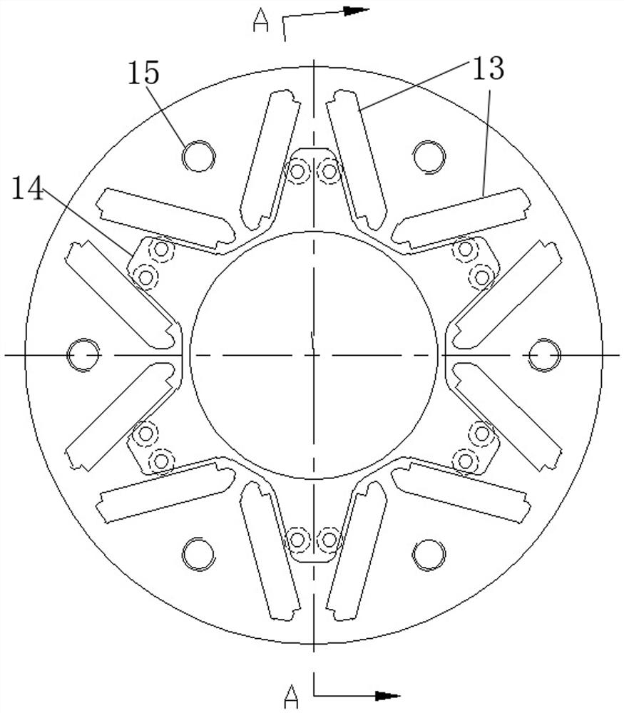
[0028] There is a positioning hole (central hole) in the center of the fixing plate 5, and there are 6 second through holes 16 on the plate, o...


PUM


Abstract

The invention relates to a dismounting technology of a permanent magnet of a permanent magnet motor, in particular to a built-in permanent magnet dismounting device and method of a permanent magnet rotor. The technical problems that the motor permanent magnet is difficult to disassemble and the permanent magnet is easy to damage are solved. A built-in permanent magnet dismounting device of a permanent magnet rotor comprises a positioning plate, a screw, a pull rod with a thread at the front end, a positioning column, a fixing plate, a nut, a positioning pin, an oil cylinder base, a bolt, an oil cylinder and a first ejector block. Compared with the design, manufacturing period, cost, management cost and the like of special equipment, the device is extremely low in manufacturing cost, does not occupy a workshop site, can be quickly assembled and disassembled, can be suitable for rotors of different models, and can completely solve the problems that an original repaired rotor permanent magnet cannot be disassembled, and the maintenance cost is high; or the rotor core punching sheet, the rotor pressing plate and the like are separated due to disassembly, the rotor core cannot be scrapped, and the rotor core is reserved.

Description

technical field [0001] The invention relates to a dismantling technology of a permanent magnet of a permanent magnet motor, in particular to a built-in permanent magnet dismantling device and method of a permanent magnet rotor. Background technique [0002] The permanent magnets of permanent magnet motors used in subways, trains, locomotives, etc. are mostly built-in. After the rotor loses magnetism due to various reasons such as motor operation or high current, it is necessary to replace some or all of the permanent magnets in the slot. After the permanent magnet, the gap in the groove has been filled with sealant, so the removal of the permanent magnet is very difficult, and the removal of the permanent magnet cannot be completed without using a special device. If the previous assembly tool is used to withdraw, it will cause the rotor pressure plate and the punching piece. Separation, delamination of punched sheets, etc., causing the rotor core to be scrapped. Therefore, ...

Claims


Application Information

Patent Timeline
Patent Type & Authority Applications(China)
IPC IPC(8): H02K15/00H02K15/03
CPCH02K15/0006H02K15/03Y02T10/64
Inventor 陈荐英支世轩程新德吉志伟苗志涛王乃让
Owner CRRC YONGJI ELECTRIC CO LTD
Learn More