Height-adjustable table
A table and height technology, applied in the table field, can solve problems such as waste, energy operation trouble, and mechanical equipment consumption, and achieve the effect of simple structure, convenient operation, and easy and convenient operation
- Summary
- Abstract
- Description
- Claims
- Application Information
AI Technical Summary
Problems solved by technology
Method used
Image
Examples
Embodiment 1
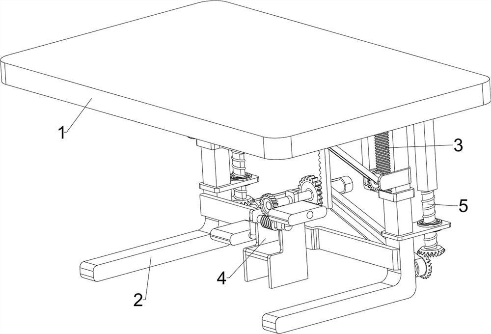
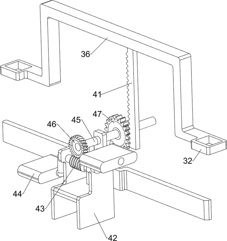
[0022] A height-adjustable table such as Figure 1-3 As shown, it includes a table board 1, a leg 2, a lifting assembly 3 and a power assembly 4. The lower part of the table board 1 is provided with legs 2 on the front and rear sides, and the leg 2 is provided with a lifting assembly 3. The legs 2 and A power assembly 4 is arranged between the lifting assemblies 3 .
[0023] When it is necessary to increase the height of the table, the power assembly 4 is controlled to operate, and the power assembly 4 will drive the lifting assembly 3 to operate, thereby causing the table board 1 to move upwards, thereby increasing the height of the table. When the height of the table needs to be adjusted lower , to control the reverse operation of the power component 4, and no longer control the power component 4 after adjustment.
[0024] The lifting assembly 3 includes a first rack 31, a guide sleeve 32, a concave block 33, a swing bar 34, a slide rail 35, a concave frame 36 and a common ...
Embodiment 2
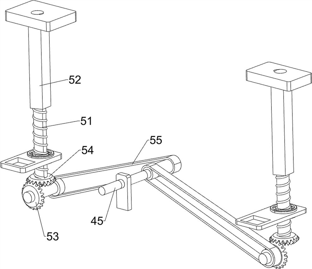
[0029] On the basis of Example 1, such as figure 1 and Figure 4 As shown, a support assembly 5 is also included. The support assembly 5 includes a screw rod 51, a threaded sleeve 52, a bevel gear shaft 53, a common bevel gear 54 and a transmission pulley set 55. The rear sides of the legs 2 are rotated through the bearing seat. Be provided with screw mandrel 51, all be connected with threaded sleeve 52 by thread on the screw mandrel 51, threaded sleeve 52 is all connected with table board 1, the bottom rear side rotation type of supporting leg 2 is provided with bevel gear shaft 53, and the screw mandrel 51 Downside key is connected with common bevel gear 54, and bevel gear shaft 53 is meshed with common bevel gear 54, is all connected with driving pulley group 55 between rotating shaft 45 and bevel gear shaft 53.
[0030] The control pedal 44 will make the rotating shaft 45 rotate, and then the bevel gear shaft 53 will be rotated through the transmission pulley group 55, an...
PUM
 Abstract
Description
Claims
Application Information
 - R&D
- Intellectual Property
- Life Sciences
- Materials
- Tech Scout
- Unparalleled Data Quality
- Higher Quality Content
- 60% Fewer Hallucinations
Browse by: Latest US Patents, China's latest patents, Technical Efficacy Thesaurus, Application Domain, Technology Topic, Popular Technical Reports.
© 2025 PatSnap. All rights reserved.Legal|Privacy policy|Modern Slavery Act Transparency Statement|Sitemap|About US| Contact US: help@patsnap.com


