Mop forming machine

A molding machine and mop technology, applied in cleaning machinery, carpet cleaning, floor cleaning, etc., can solve the problems of high structural failure rate, surface wear of mop rod, large outward centrifugal force of the claw grasping device, etc., and achieve stable operation structure. , The effect of stable structure and convenient operation

Pending Publication Date: 2021-04-30
苍南县方舟家居用品有限公司
View PDF0 Cites 0 Cited by
  • Summary
  • Abstract
  • Description
  • Claims
  • Application Information

AI Technical Summary

Problems solved by technology

There are following problems in this kind of structure: 1. The claw grabbing device grabs and fixes the lower end of the mop rod through a plurality of claws, so the claws are inevitably subjected to the torque force generated when the mop rod rotates, and the mop rod Due to its own gravity and the outward centrifugal force generated by the rotation of the mop rod, it is often prone to breakage and damage, and the structural failure rate is high
2. The structure of the claw grabbing device is precise, and if one of the claws is damaged, multiple claws must be disassembled. In addition, the claws are often shrunk in the cavity, which is very inconvenient for replacement and maintenance
3. The claw grabbing device is located at the lower end of the mop rod. If the distance between the mop rod and the limit sleeve is too tight during the rotation, it will easily cause the mop rod to rotate poorly and cause wear on the surface of the mop rod. If it is too large, it is easy to cause the centrifugal force of the mop rod to be in an inclined state instead of a vertical state, so it is easy to generate a large outward centrifugal force on the claw grabbing device, and it is easy to cause the winding position of the cleaning thread to shift

Method used


Image

  • Mop forming machine
  • Mop forming machine
  • Mop forming machine

Examples


Embodiment

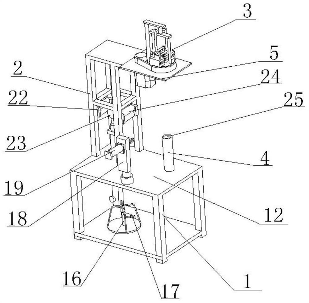
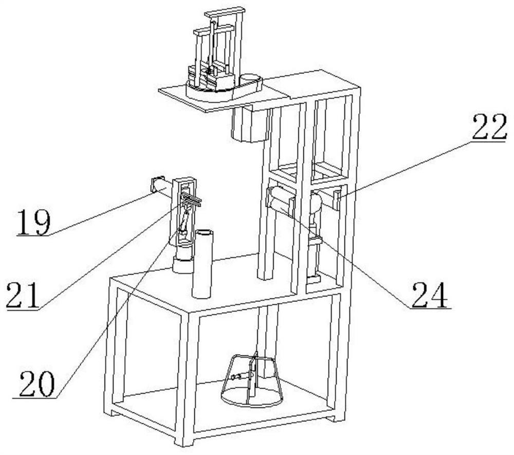
[0028] Embodiment: A mop forming machine, including a base 1, an upper bracket 2, a clamping rotation unit, an outlet unit, a power output unit, and a control center respectively connecting the clamping rotation unit, the outlet unit, and the power output unit. An operating platform 12 is provided on the upper surface of the base 1 , and the upper bracket 2 is fixedly installed on the operating platform 12 . The clamping rotation unit includes a clamping rotation device 3 and a limit support device 4 , and the clamping rotation device 3 is installed on the upper end of the upper bracket 2 . The clamping hole 7 corresponding to the limit support device 4 is provided at the lower end of the clamping and rotating device 3 , and the clamping and rotating device 3 can clamp and rotate the mop rod.

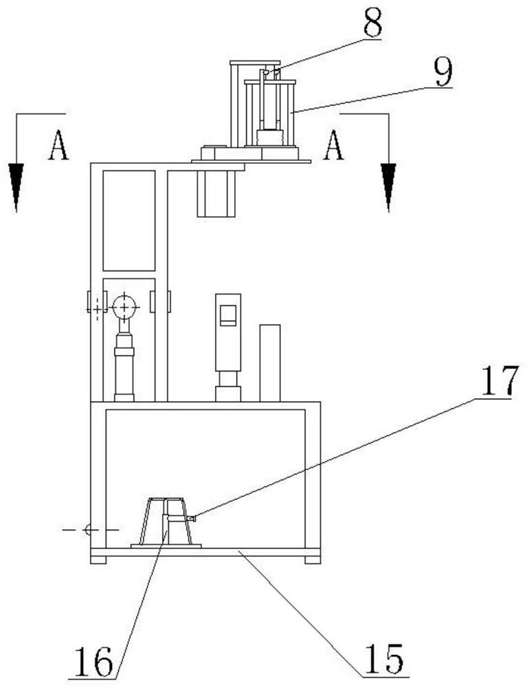
[0029] The clamping and rotating device 3 includes a driving motor 5, a movable turntable 6, a clamping assembly, a rotary joint 8, and a rotating bracket 9. The driving motor 5 and the...


PUM


Abstract

The invention discloses a mop forming machine, which comprises a base, an upper support, a clamping and rotating unit, a wire outlet unit, a power output unit and a control center, wherein an operation table is arranged on the upper end face of the base, and the upper support is fixedly installed on the operation table; the clamping and rotating unit comprises a clamping and rotating device and a limiting and supporting device, the clamping and rotating device is installed at the upper end of the upper support, a clamping hole corresponding to the limiting and supporting device is formed in the lower end of the clamping and rotating device, the clamping and rotating device can clamp and rotate the mop rod, the limiting and supporting device is installed on the operation table, and the limiting and supporting device is used for limiting and supporting the lower part or the lower end of the mop rod; and the wire outlet unit comprises a pay-off rack and a wire leading mechanism, the wire outlet unit can lead out a winding wire and guide the winding wire to the mop head, the power output unit is connected with the control center, and the control center is connected with the clamping and rotating unit and the wire outlet unit.

Description

technical field [0001] The invention relates to the field of textile machinery, in particular to a mop forming machine. Background technique [0002] The operation mode of the traditional mop forming machine is as follows: firstly, the lower end of the mop rod is fixed by a claw grabbing device similar to a three-catch chuck, and then the whole mop rod is driven to rotate, and finally the cleaning thread is fixed on the lower part of the mop rod by winding wires. Form a mop head. There are following problems in this kind of structure: 1. The claw grabbing device grabs and fixes the lower end of the mop rod through a plurality of claws, so the claws are inevitably subjected to the torque force generated when the mop rod rotates, and the mop rod Due to its own gravity and the outward centrifugal force generated by the rotation of the mop rod, it is often prone to breakage and damage, and the structural failure rate is high. 2. The structure of the claw grabbing device is pre...

Claims


Application Information

Patent Timeline
IPC IPC(8): A47L13/20A47L13/42A47L13/44
CPCA47L13/20A47L13/42A47L13/44
Inventor 董希忠
Owner 苍南县方舟家居用品有限公司
Why Eureka
Try Eureka