
Crushed peanut processing equipment capable of reducing residual oil

A processing equipment and peanut crushing technology, which is applied in centrifuges with rotating drums, solid separation, grading, etc., can solve the problems of poor taste, unhealthy peanut crushing, and low yield of peanut crushing

Active Publication Date: 2021-04-30
阜阳佰恩得新材料技术有限公司
View PDF7 Cites 0 Cited by
  • Summary
  • Abstract
  • Description
  • Claims
  • Application Information

AI Technical Summary

Problems solved by technology

[0004] However, in this technical solution, crushing is used to make crushed peanuts, and the particle size cannot be guaranteed during the crushing process. Particle uniformity cannot be guaranteed for some occasions with high particle size requirements, and the mixing of large and small particles cannot meet high-demand occasions. Requirements, and too much crumbs lead to low yield of crushed peanuts;
[0005] Insufficient draining of partially fried peanuts leads to too much residual oil when making crushed peanuts, which leads to poor taste of crushed peanuts and is not conducive to people's health

Method used


Image

  • Crushed peanut processing equipment capable of reducing residual oil
  • Crushed peanut processing equipment capable of reducing residual oil
  • Crushed peanut processing equipment capable of reducing residual oil

Examples


Embodiment 1

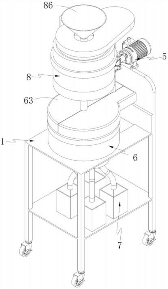
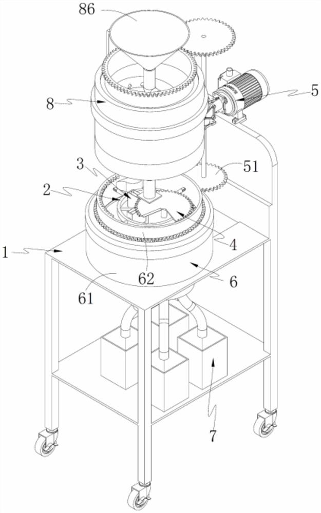
[0056] like Figure 1-2 As shown, a crushed peanut processing equipment for reducing residual oil, comprising a rack 1, and also comprising:

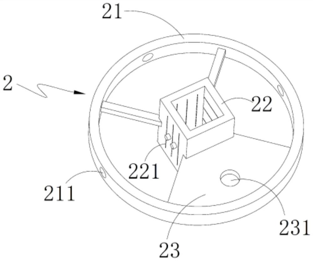
[0057] Tool holder unit 2, such as image 3 As shown, the tool holder unit 2 is arranged on the frame 1, which includes an annular connecting frame 21 and a tool holder 22 arranged on the annular connecting frame 21. The tool holder 22 is hollow in design, and its three sides are The guide grooves 221 are evenly distributed, and the other side thereof is provided with a connecting plate 23 connecting the tool holder 22 and the annular connecting frame 21. The connecting plate 23 is provided with a through hole a231; There are three guide holes 211;

[0058] Three cutters 3 matched with the guide holes 211, such as Figure 4 As shown, the cutting knife 3 includes a set of cutting edges 31 and a cutting rod 32 connected with a set of cutting edges 31, the set of cutting edges 31 is matched with the guide groove 221, and the cutting rod...

Embodiment 2

[0086] like Figure 13-17 As shown in the figure, the same or corresponding parts as in the first embodiment are marked with the corresponding reference numerals as in the first embodiment. For the sake of brevity, only the differences from the first embodiment are described below; the difference between the second embodiment and the first embodiment The point is:

[0087] like Figure 13 As shown, the drive unit 5 drives the annular control disc 62 to rotate, the annular control disc 62 drives the feed control unit 4 to rotate, and the discharge opening 432 on the feeding plate 43 turns over the knife rest 22, so that the bottom of the knife rest 22 is closed, At this time, the feeding opening 422 on the dividing plate 42 is communicated with the knife holder 22; the drive unit 5 drives the conical rotating disk 83 to rotate, the fried peanuts are added to the feeding hopper 86, and the peanuts rotate synchronously along the spiral oil draining pipe 84 and descend downward. ...


PUM


Abstract

The invention provides crushed peanut processing equipment capable of reducing residual oil. The equipment comprises a rack, a knife rest unit, a cutter, a feeding control unit, a driving unit, a material cutting control unit, a material receiving unit and an oil draining unit, and is characterized in that a spiral oil draining pipe of which a spiral direction is opposite to a rotating direction of a conical rotating disc is arranged on the oil draining unit, so that oil draining and sorting of fried peanuts are achieved, and the peanuts subjected to oil draining sequentially enter a knife rest; the feeding control unit, the knife rest unit, the cutter and the material cutting control unit cooperate with one another, so that the peanuts are cut according to a required particle size, and the problem that the particle uniformity of crushed peanuts is poor due to the fact that the crushed peanuts are produced in a crushing mode is solved; and the crushed peanuts with different particle sizes are classified and collected by means of the material receiving unit, the crushed peanuts with the different particle sizes are independently packaged and sold, the requirements of different customers are met, and a yield of the crushed peanuts is increased.

Description

technical field [0001] The invention relates to the technical field of food processing, in particular to crushed peanut processing equipment for reducing residual oil. Background technique [0002] Crushed peanuts are an indispensable ingredient in traditional Chinese cuisine. Peanuts can be added to hot pot, toast, cold dishes, snacks, etc. to make the food more delicious. [0003] Chinese invention patent 201810091786.0 discloses a crushed peanut processing device for food processing, which belongs to the field of food processing equipment. The crushing device is installed on the top of the second bracket, the top of the screen is connected with the first bracket and the second bracket, two of the baffles are respectively fixed on the left and right sides of the screen, and the collection tank is fixed On the square hole at the front end of the workbench, the workbench is a rectangular iron plate, the storage tank is fixed above the workbench, the first motor is fixed on ...

Claims


Application Information

Patent Timeline
IPC IPC(8): B02C18/02B02C18/04B02C23/16B02C23/14B07B13/07B04B1/00B04B9/08A23L25/00
CPCB02C18/02B02C18/04B02C23/16B02C23/14B07B13/07B04B1/00B04B9/08A23L25/00B02C2023/165
Inventor 张国金
Owner 阜阳佰恩得新材料技术有限公司
Learn More