Filter screen cleaning structure

A technology of filter screen and filter screen plate, which is applied in the direction of filter screen, cleaning method and utensils, cleaning method using gas flow, etc., which can solve the problem of impurities and sludge remaining, filter screen clogging, and reduction of filter filtering effect, etc. question

Active Publication Date: 2021-04-30
山东凤鸣桓宇环保有限公司
View PDF10 Cites 1 Cited by
  • Summary
  • Abstract
  • Description
  • Claims
  • Application Information

AI Technical Summary

Problems solved by technology

[0004] The purpose of the present invention is to solve the problem in the prior art that "a lot of impurities and sludge will remain on the filter screen after the sewage is filtered. If the

Method used

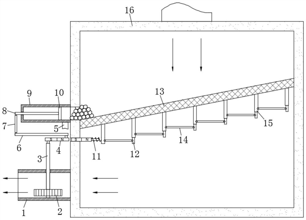

Image

  • Filter screen cleaning structure
  • Filter screen cleaning structure
  • Filter screen cleaning structure

Examples


Embodiment Construction

[0017] The following will clearly and completely describe the technical solutions in the embodiments of the present invention with reference to the accompanying drawings in the embodiments of the present invention. Obviously, the described embodiments are only some, not all, embodiments of the present invention.

[0018] In describing the present invention, it should be understood that the terms "upper", "lower", "front", "rear", "left", "right", "top", "bottom", "inner", " The orientation or positional relationship indicated by "outside", etc. is based on the orientation or positional relationship shown in the drawings, and is only for the convenience of describing the present invention and simplifying the description, rather than indicating or implying that the referred device or element must have a specific orientation, so as to Specific orientation configurations and operations, therefore, are not to be construed as limitations on the invention.

[0019] refer to Figure ...


PUM


Abstract

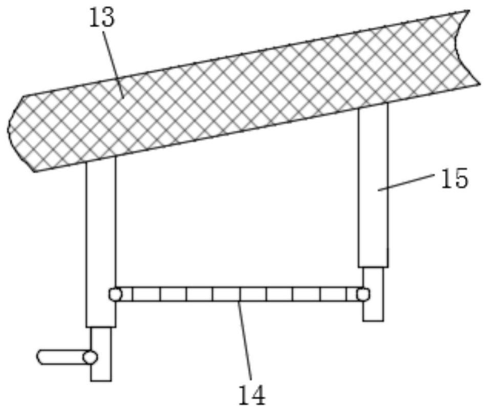
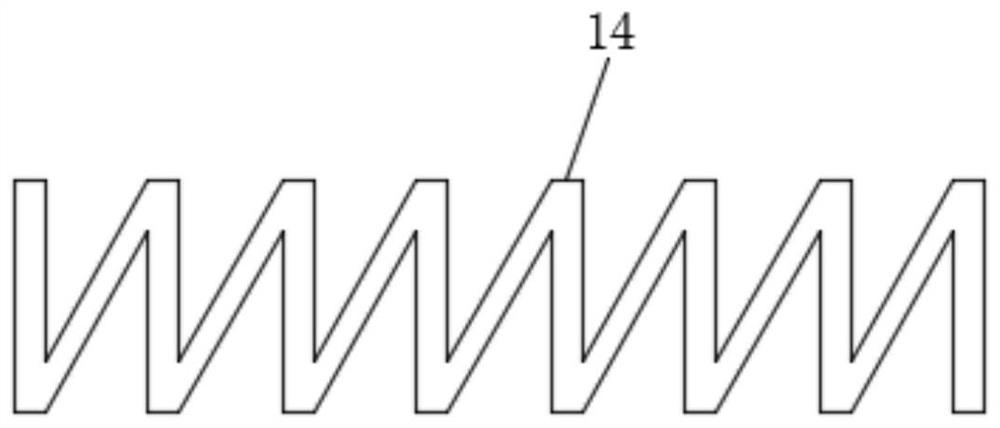
The invention discloses a filter screen cleaning structure. The filter screen cleaning structure comprises a shell, wherein a filter screen plate is obliquely arranged in the shell, a discharging opening is formed in the left side wall of the shell, a sealing pipe is fixedly mounted on the left side wall of the shell, an opening in the right end of the sealing pipe corresponds to the discharging opening, a liquid discharging pipe is fixedly mounted on the side wall of the lower end of the shell, the right end of the liquid discharging pipe penetrates through the side wall of the shell and communicates with the interior of the shell, an impeller is arranged in the liquid discharging pipe, a connecting rod is vertically inserted in the center of the impeller in a penetrating mode, the lower end of the connecting rod is rotationally connected to the bottom end face in the liquid discharging pipe, the upper end of the connecting rod penetrates through the upper end face of the liquid discharging pipe and is rotationally connected to a magnetic rotary disc. According to the structure, sludge and impurities can conveniently enter the sealing pipe along the discharging opening at the lower end of the inclined surface of the filter screen plate to be collected and recycled, so that meshes in the filter screen plate are prevented from being blocked by the sludge impurities, and the filtering effect of a filter is ensured.

Description

technical field [0001] The invention relates to the technical field of environmental protection, in particular to a filter screen cleaning structure. Background technique [0002] After the sewage is filtered, a lot of impurities and sludge will remain on the filter screen. If the filter screen cannot be cleaned in time, the filter screen will be blocked and the filtering effect of the filter will be reduced. [0003] In order to solve the above problems, the present invention proposes a filter screen cleaning structure. Contents of the invention [0004] The purpose of the present invention is to solve the problem in the prior art that "a lot of impurities and sludge will remain on the filter screen after the sewage is filtered. If the filter screen cannot be cleaned in time, the filter screen will be blocked and the filtering effect of the filter will be reduced." "Defect, thus proposes a kind of screen cleaning structure. [0005] In order to achieve the above object,...

Claims


Application Information

Patent Timeline
IPC IPC(8): B07B1/34B07B1/42B07B1/54B08B5/04B08B13/00
CPCB07B1/343B07B1/42B07B1/54B08B5/04B08B13/00
Inventor 刘善才
Owner 山东凤鸣桓宇环保有限公司
Why Eureka
Try Eureka