Environment-friendly processing device for machining waste chips

A technology of environmental protection treatment and mechanical processing, which is applied in the direction of wood processing equipment, manufacturing tools, bark area/debris/dust/waste removal, etc., which can solve the inconvenient recycling, inconvenient cleaning of waste, and waste debris with many impurities To achieve the effect of enriching the functions of the device, facilitating recycling, and improving the cleaning effect

Inactive Publication Date: 2018-12-07
江西佰嘉实业有限公司
View PDF7 Cites 1 Cited by
  • Summary
  • Abstract
  • Description
  • Claims
  • Application Information

AI Technical Summary

Problems solved by technology

[0003] Waste chips will be generated during mechanical processing, which needs to be collected and recycled. The existing waste chip collection device has a single function, which makes it inconvenient to clean the waste chips. The collected waste chips have many impurities and are inconvenient to recycle. Therefore, a An environmental protection treatment device for machining waste

Method used


Image

  • Environment-friendly processing device for machining waste chips
  • Environment-friendly processing device for machining waste chips
  • Environment-friendly processing device for machining waste chips

Examples


Embodiment 1

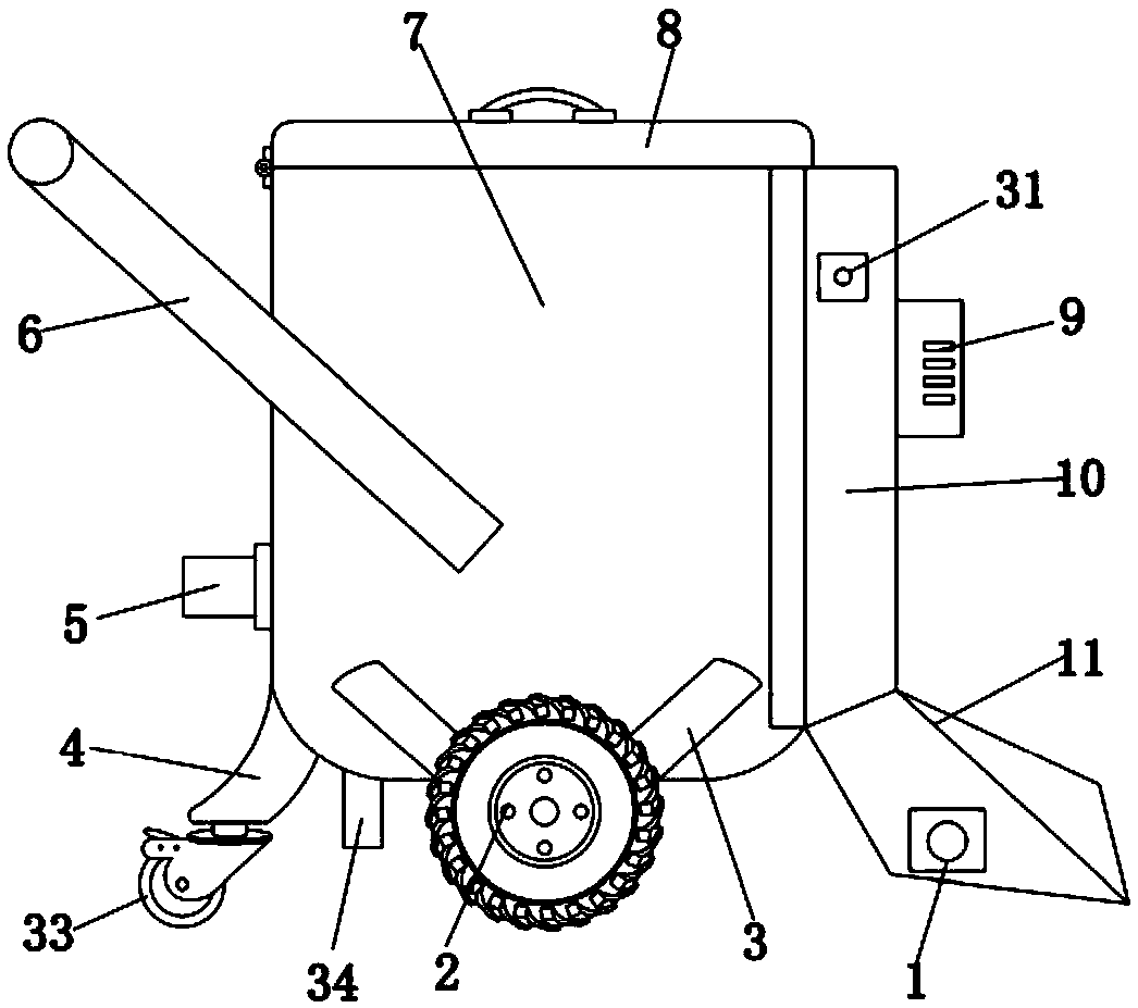
[0046] Example 1 reference Figure 1-5 , an environmental protection treatment device for machining waste, including a metal cylinder 7, a cylinder cover 8 is hinged on the outer wall of the top side of the metal cylinder 7, a handrail frame 6 is fixed on the outer wall of the metal cylinder 7 by bolts, and the outer walls of the metal cylinder 7 are on both sides. Brackets 3 are welded, and the side walls of the two brackets 3 are movably connected with wheels 2. The side of the metal cylinder 7 away from the armrest frame 6 is provided with a suction mechanism 28. The suction mechanism includes a metal cover 10, and the bottom end of the metal cover 10 is welded with a The suction hopper 11 is inclined. The inner wall of the suction hopper 11 is provided with a cleaning mechanism 30. The suction mechanism cooperates with the cleaning roller 17 to facilitate the collection and recycling of waste on the machined ground, which is conducive to the preliminary screening of iron wa...

Embodiment 2

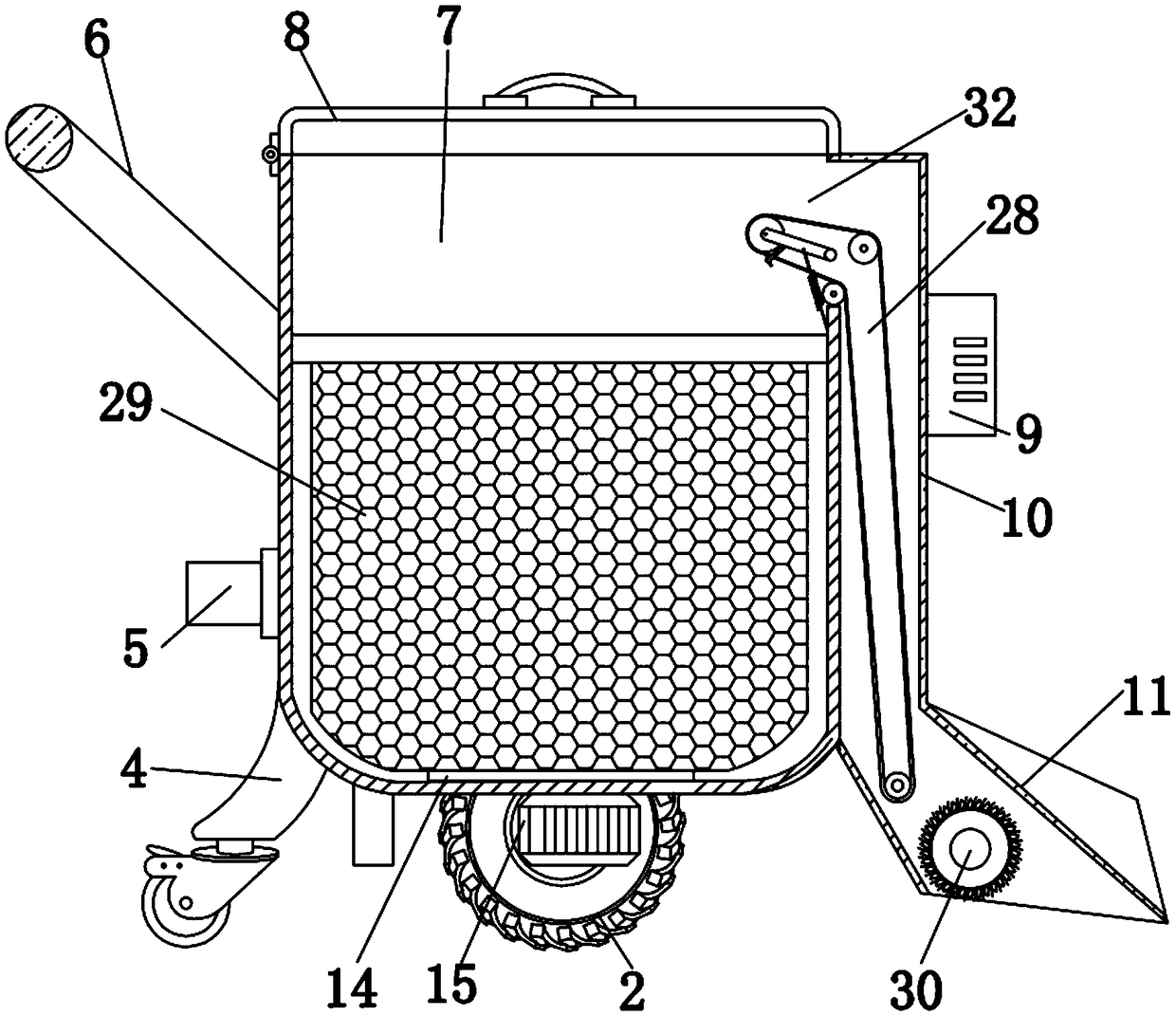
[0047] Example two reference Figure 1-5 , the filter mechanism includes a first metal mesh cylinder 13, and the top position of the side wall of the first metal mesh cylinder 13 is sleeved with a bearing ring 12, and the side wall of the bearing ring 12 is clamped with the inner wall of the metal cylinder 7 near the bottom end of the feed hole The inner wall of the first metal mesh cylinder 13 is sleeved with a second metal mesh cylinder 25, and the inner walls of both sides of the second metal mesh cylinder 25 are welded with handles 24, and the inner wall of the bottom end of the metal cylinder 7 is fixed with a bearing turntable 14 by bolts, And the top of the bearing turntable 14 is fixed to the outer wall of the bottom end of the first metal mesh cylinder 13 by bolts, the middle position of the outer wall of the bottom end of the metal cylinder 7 is fixed with a third motor 15 by bolts, and the output shaft of the third motor 15 passes through the bottom end of the metal ...

Embodiment 3

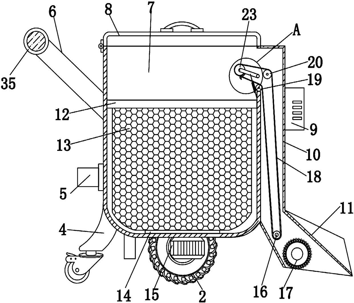
[0048] Example three reference Figure 1-5 , the cleaning mechanism includes a cleaning roller 17, the cleaning roller 17 is movably connected with the inner wall of the suction hopper 11, the side wall of the suction hopper 11 is fixed with a first motor 1 by bolts, and the output shaft of the first motor 1 passes through the outer wall of one side of the suction hopper 11 One end of the cleaning roller 17 is fixed by bolts.


PUM


Abstract

The invention discloses an environment-friendly processing device for machining waste chips. The environment-friendly processing device for the machining waste chips comprises a mental barrel, a barrel cover is hinged to the outer wall of one side of the top end of the metal barrel, the outer wall of one side of the metal barrel is fixedly provided with an armrest frame through bolts, supports areconnected to the outer walls of the two sides of the metal barrel in a welded mode, a wheel is movably connected to the side walls of the two supports, a material sucking mechanism is arranged on oneside, far away from the armrest frame, of the metal barrel, the material sucking mechanism comprises a metal cover, a suction hopper which is obliquely arranged is connected with the bottom end of the metal cover in a welded mode, a cleaning mechanism is arranged on the inner wall of the suction hopper, a negative pressure fan is fixedly arranged on the side wall of the metal cover through bolts,the negative pressure fan communicates with the inner wall of the metal cover, and a first roller is movably connected to the top end of the inner wall of the suction hopper. According to the environment-friendly processing device for the machining waste chips, the collected waste chips can be cleaned, functions of the device are enriched, the waste chips can be recycled conveniently and separated conveniently from other impurities, so that purity of the waste chips can be improved; and the waste chips can be conveniently driven to overturn, the cleaning effect of the waste chips can be improved, and the waste chips can be conveniently taken out.

Description

technical field [0001] The invention relates to the technical field of waste collection devices, in particular to an environmental protection treatment device for machining waste. Background technique [0002] The production process of a machine refers to the entire process of making a product from raw materials (or semi-finished products). For machine production, it includes transportation and storage of raw materials, preparation for production, manufacturing of blanks, processing and heat treatment of parts, assembly and debugging of products, painting and packaging, etc. The content of the production process is very extensive. Modern enterprises use the principles and methods of systems engineering to organize and guide production, and regard the production process as a production system with input and output. [0003] Waste chips will be generated during mechanical processing, which needs to be collected and recycled. The existing waste chip collection device has a sin...

Claims


Application Information

Patent Timeline
Patent Type & Authority Applications(China)
IPC IPC(8): B27G3/00
CPCB27G3/00
Inventor 不公告发明人
Owner 江西佰嘉实业有限公司
Why Eureka
Try Eureka