Environment-friendly treatment equipment for contaminated soil

A polluted soil and environmental protection technology, applied in the restoration of polluted soil, soil lifting machinery, agricultural machinery and tools, etc., can solve the problems of poor portability, low treatment efficiency, inconvenient soil treatment, etc., and achieve comprehensive irrigation and lifting effects Effect

Active Publication Date: 2021-04-30
浙江天弈环境有限公司
View PDF6 Cites 4 Cited by
  • Summary
  • Abstract
  • Description
  • Claims
  • Application Information

AI Technical Summary

Problems solved by technology

[0004] The purpose of the present invention is to solve the shortcomings of poor portability of soil treatment equipment in the prior art, inconvenient

Method used


Image

  • Environment-friendly treatment equipment for contaminated soil
  • Environment-friendly treatment equipment for contaminated soil
  • Environment-friendly treatment equipment for contaminated soil

Examples


Embodiment 1

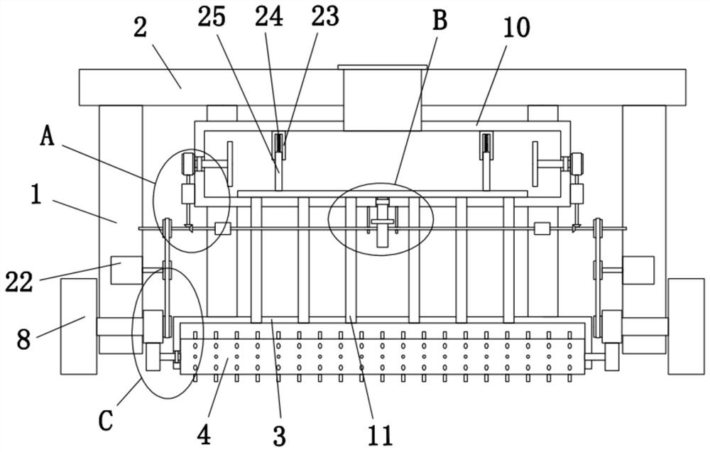
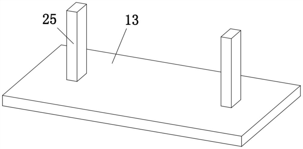
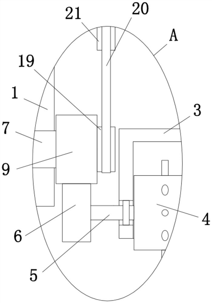
[0030] refer to Figure 1-5, a polluted soil environmental protection treatment equipment, comprising two fixed plates 1, the top of the two fixed plates 1 is fixedly installed with a top plate 2, the bottom of the top plate 2 is fixedly installed with two support plates, and the bottom of the two support plates is fixedly installed with The same fixed sleeve 3, the bottom of the fixed sleeve 3 is an opening, and the inner walls of both sides of the fixed sleeve 3 are provided with rotating holes, and connecting rods 5 are installed in the two rotating holes, and the ends of the two connecting rods 5 are close to each other. The same tilling roller 4 is fixedly installed, the first gear 6 is fixedly installed at the ends of the two connecting rods 5 away from each other, and a through hole is opened on one side of the two fixing plates 1, and the two through holes are rotated and installed There are fixed blocks 7, and the ends of the two fixed blocks 7 that are far away from ...

Embodiment 2

[0039] refer to Figure 1-5 , a polluted soil environmental protection treatment equipment, comprising two fixing plates 1, the tops of the two fixing plates 1 are fixed with a top plate 2 by bolts, and the bottom of the top plate 2 is fixed with two support plates by bolts, the two support plates The bottom is fixed with the same fixed sleeve 3 by bolts, the bottom of the fixed sleeve 3 is an opening, the inner walls on both sides of the fixed sleeve 3 are provided with rotating holes, and connecting rods 5 are installed in the two rotating holes, and the two connecting One end of the rods 5 close to each other is fixed with the same turning roller 4 through bolts, and the ends of the two connecting rods 5 away from each other are fixed with the first gear 6 through bolts, and one side of the two fixed plates 1 is provided with a through hole. The two through holes are equipped with a fixed block 7 for rotation, and the ends of the two fixed blocks 7 that are far away from ea...


PUM


Abstract

The invention belongs to the field of environment-friendly treatment equipment, particularly relates to environment-friendly treatment equipment for contaminated soil, and aims to solve the problems that existing soil treatment equipment is poor in portability, inconvenient for direct treatment in soil, low in treatment efficiency and poor in soil treatment effect. The equipment comprises two fixing plates, a top plate is fixedly mounted at the tops of the two fixing plates, two support plates are fixedly mounted at the bottom of the top plate, the same fixing sleeve is fixedly mounted at the bottoms of the two support plates, an opening is formed in the bottom of the fixing sleeve, rotating holes are formed in the inner walls of the two sides of the fixing sleeve, connecting rods are rotatably mounted in the two rotating holes, and the ends, close to each other, of the two connecting rods are fixedly provided with a same soil turning roller. The soil treatment equipment is reasonable in structure, convenient to operate, good in portability, capable of facilitating direct treatment in soil, high in treatment efficiency and good in soil treatment effect.

Description

technical field [0001] The invention relates to the technical field of environmental protection treatment equipment, in particular to an environmental protection treatment equipment for polluted soil. Background technique [0002] The erosion of pollutants on the soil is becoming more and more serious. Soil pollution will directly change the composition and physical and chemical properties of the soil, destroy the normal function of the soil, and through the process of plant absorption and food chain accumulation, and then pose a threat to human health. Harm, when the soil contains too many harmful substances, exceeding the self-purification capacity of the soil, the composition, structure and function of the soil will change, the microbial activity will be inhibited, and the harmful substances or their decomposition products will gradually accumulate in the soil and pass through the soil to plants. Then to the human body, or through the soil to water and then to the human b...

Claims


Application Information

Patent Timeline
IPC IPC(8): B09C1/08A01B77/00
CPCB09C1/08A01B77/00B09C2101/00
Inventor 谭翔
Owner 浙江天弈环境有限公司
Why Eureka
Try Eureka