Rotary and planar scanning positioning mechanism

A technology of positioning mechanism and plane scanning, which is used in motor vehicles, metal processing, metal processing equipment, etc.

Active Publication Date: 2021-04-30
CHINA ELECTRIC POWER RES INST
View PDF5 Cites 1 Cited by
  • Summary
  • Abstract
  • Description
  • Claims
  • Application Information

AI Technical Summary

Problems solved by technology

[0016] In the prior art, robots cannot identify tasks at fixed points

Method used


Image

  • Rotary and planar scanning positioning mechanism
  • Rotary and planar scanning positioning mechanism
  • Rotary and planar scanning positioning mechanism

Examples


Embodiment 1

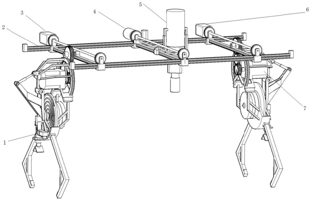
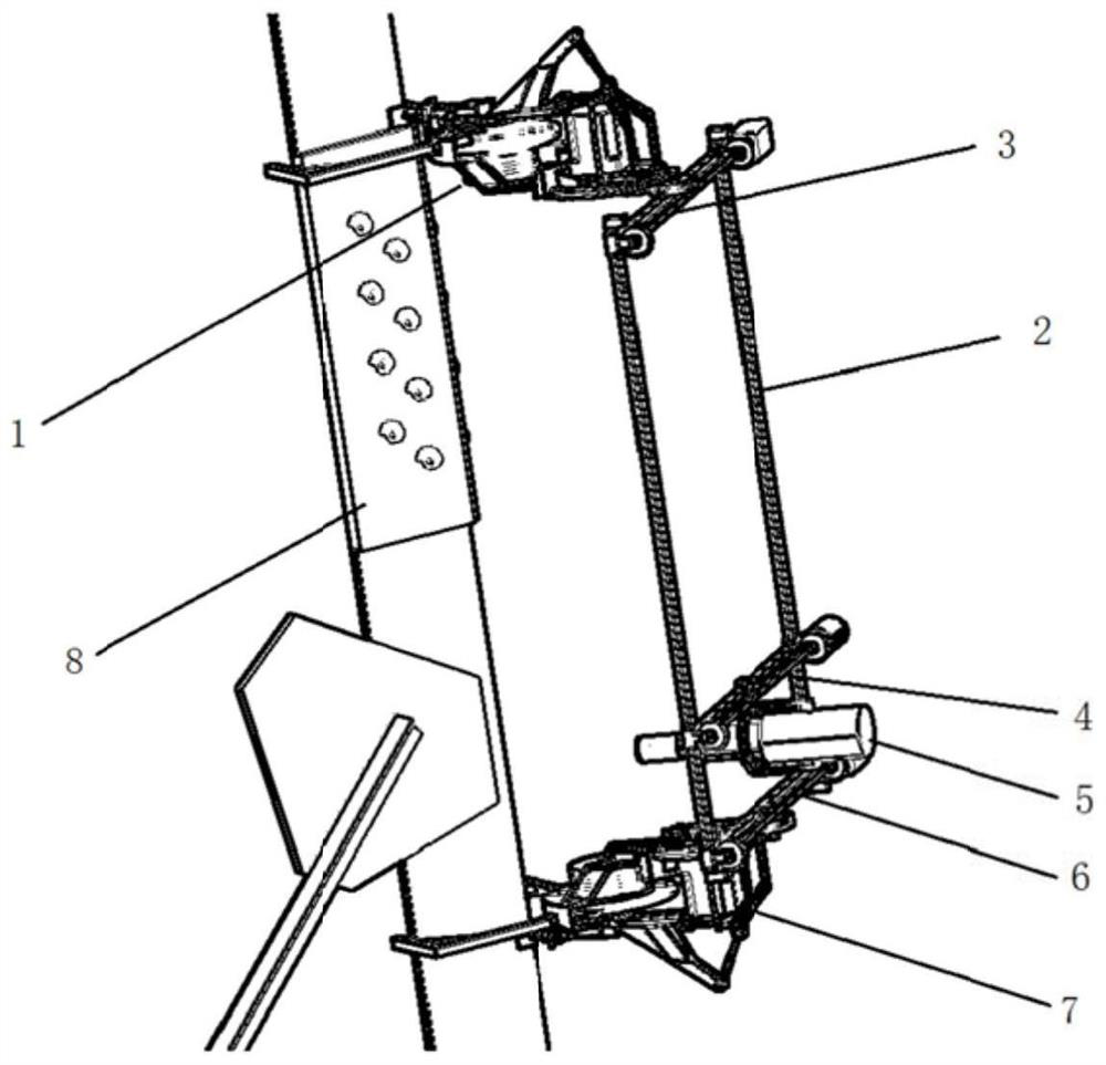
[0076] Embodiment 1, combining figure 1 The present invention provides a rotation and plane scanning positioning mechanism, a robot frame, an intermediate mechanism 7 and a clamping mechanism 1 arranged on the same side as the robot frame; the clamping mechanism 1 is connected with the robot frame through the intermediate mechanism 7, and includes a 202 track 2, crossbar, camera 504 and intermediate mechanism 7;

[0077] The camera 504 is arranged on the crossbar, which is vertically arranged on the track 2, and the intermediate mechanism 7 is connected with the crossbar, and the intermediate mechanism 7 is used to rotate the crossbar.

[0078] There are multiple cross bars, all of which are arranged on the guide rod, and the cross bars arranged on both sides of the guide rod are connected with the intermediate mechanism 7;

[0079] The camera 504 is arranged on a crossbar installed in the middle of the track 2 .

[0080] The crossbar in the middle includes: slide rails, lea...

Embodiment 2

[0096] In order to realize a robot technology and product capable of autonomous climbing, tower body attachment and working position locking, bolt identification, positioning and fully automatic fastening operations, the present invention mainly solves the following technical problems:

[0097] (1 the structural form of existing climbing robot can't adapt to the rigid structure climbing of this kind of angle steel tower with complex surface obstacle.

[0098] (2 the existing iron tower climbing robot can't realize the effective attachment and locking at any part of the angle steel tower body, and carry out the operation of the tower body with tools.

[0099] (3 The foot structure of the existing iron tower climbing robot is complex and difficult to control, and it is impossible to realize effective clamping at the position where there are obstacles on the surface of the angle steel tower, such as the connecting plate and the foot nail, and the mechanical self-locking property i...

Embodiment 3

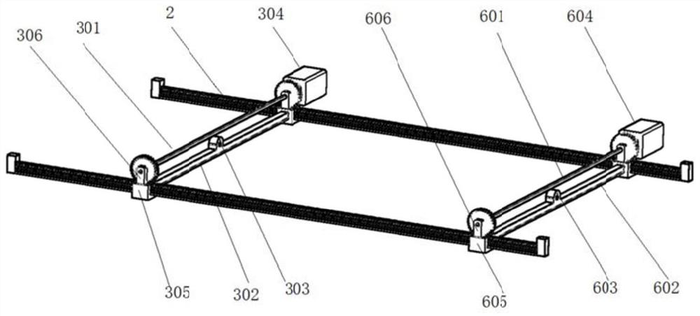
[0119] In the present invention, the front foot moving crossbar 3, the rear foot moving crossbar 6 and the middle moving crossbar 4 are arranged on the track 2, so that the three crossbars can move on the track 2;

[0120] The track 2 includes: a track plug 201, a rack 202, a slide rail 203, the rack 202 and the slide rail 203 are axially connected in parallel and the axis is in a vertical plane, and the track plug 201 is arranged at both ends of the slide rail 203;

[0121] The forefoot moving crossbar 3 includes: the forefoot moving crossbar linkage gear 301, the forefoot auxiliary moving crossbar 302, the forefoot keyway connection part 303, the front foot main moving crossbar stepper motor 304, the forefoot moving crossbar chute 305, the forefoot moving crossbar The lug 306, the main cross bar and the auxiliary cross bar are arranged in parallel, and the two ends are sequentially connected to the front foot mobile cross bar linkage gear 301, the front foot mobile cross bar ...


PUM


Abstract

The invention relates to a rotary and planar scanning positioning mechanism. The rotary and planar scanning positioning mechanism comprises a robot framework, a middle mechanism (7) and a clamping mechanism (1), wherein the middle mechanism (7) and the clamping mechanism (1) are arranged on the same side of the robot framework. The clamping mechanism (1) is connected with the robot framework through the middle mechanism (7) and comprises a rail (2) with a rack (202), a transverse rod, a camera (504) and the middle mechanism (7). The camera (504) is arranged on the transverse rod. The transverse rod is perpendicularly arranged on the rail (2). The middle mechanism (7) is connected with the transverse rod and used for rotating the transverse rod. According to the rotary and planar scanning positioning mechanism, the transverse rod is arranged on the rail and controlled to rotate through rotation of the middle mechanism, the camera on the robot framework can check a transmission tower in all directions, and flaw detection and paint spraying of angle steel structural parts are achieved through fastening operation of fastening tools on lever-connected bolts of angle steel towers.

Description

technical field [0001] The invention relates to a mechanical structure and its control technology, in particular to a rotation plus plane scanning positioning mechanism. Background technique [0002] As one of the main sub-projects in the construction of transmission line projects, tower assembly construction requires heavy bolt tightening workload and high torque accuracy requirements after the tower materials are hoisted in place. The fastness of the main material bolts of the angle steel tower plays an important role in the anti-vibration performance and overall structural stability of the iron tower. [0003] At present, the fastening of angle steel tower bolts mainly relies on manual operation with the help of simple tools or electric wrenches; after the line is put into operation, it is necessary to regularly monitor the tightening torque of the main material bolts of angle steel towers, so as to loosen nuts with unqualified torque. Retightening, such retightening is ...

Claims


Application Information

Patent Timeline
Patent Type & Authority Applications(China)
IPC IPC(8): B23P19/06B62D57/024
CPCB23P19/06B62D57/024
Inventor 万建成胡春华江明赵飞
Owner CHINA ELECTRIC POWER RES INST
Why Eureka
Try Eureka