
Surface fine polishing device based on PS plate production

A fine and grinding mechanism technology, which is applied in the direction of grinding drive devices, machine tools suitable for grinding workpiece planes, grinding machines, etc., can solve the problems of low working efficiency and uneven grinding of PS boards, and achieve good grinding effects and improved Work efficiency, convenient work effect

Active Publication Date: 2021-04-30
南丰县致诚科技有限公司
View PDF15 Cites 5 Cited by
  • Summary
  • Abstract
  • Description
  • Claims
  • Application Information

AI Technical Summary

Problems solved by technology

[0004] In order to overcome the disadvantages of manual polishing of PS boards, such as low work efficiency and easy grinding unevenness, the technical problem to be solved is: to provide a kind of material that can automatically load, fix, and polish PS boards and has a good grinding effect. Surface fine grinding device based on PS board production

Method used


Image

  • Surface fine polishing device based on PS plate production
  • Surface fine polishing device based on PS plate production
  • Surface fine polishing device based on PS plate production

Examples


Embodiment 1

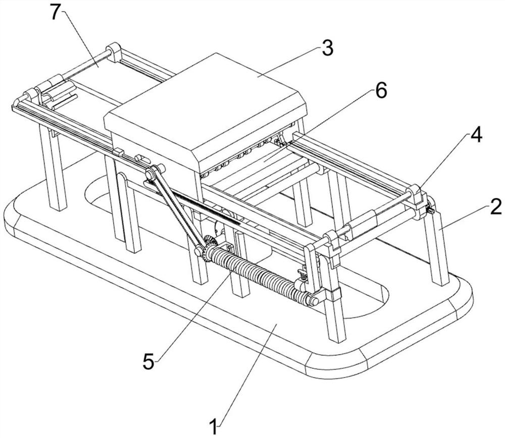
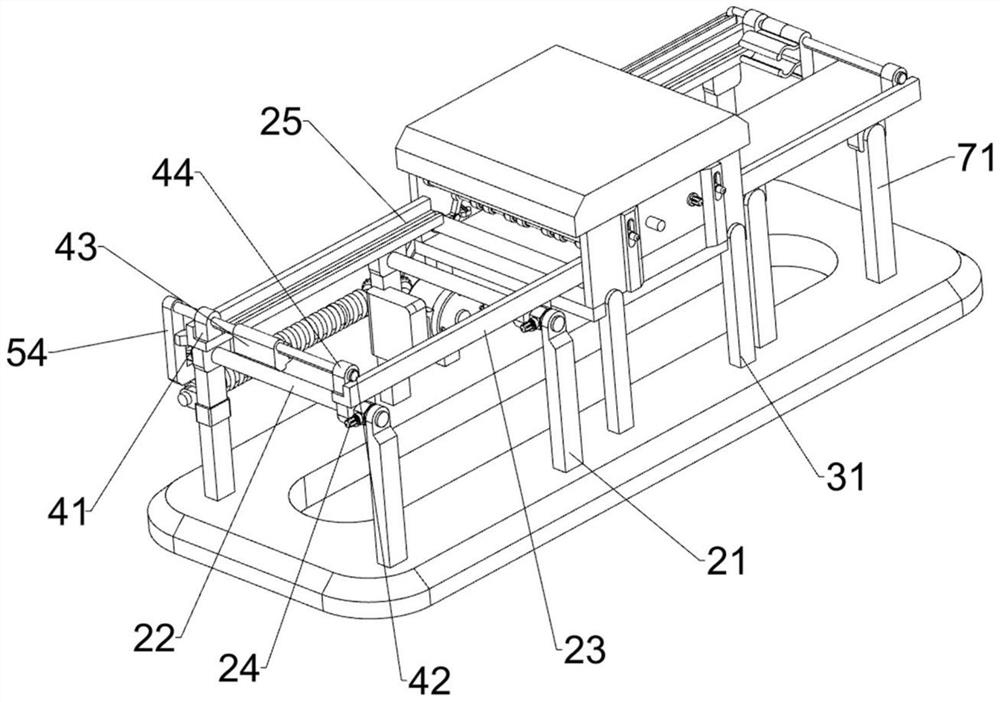
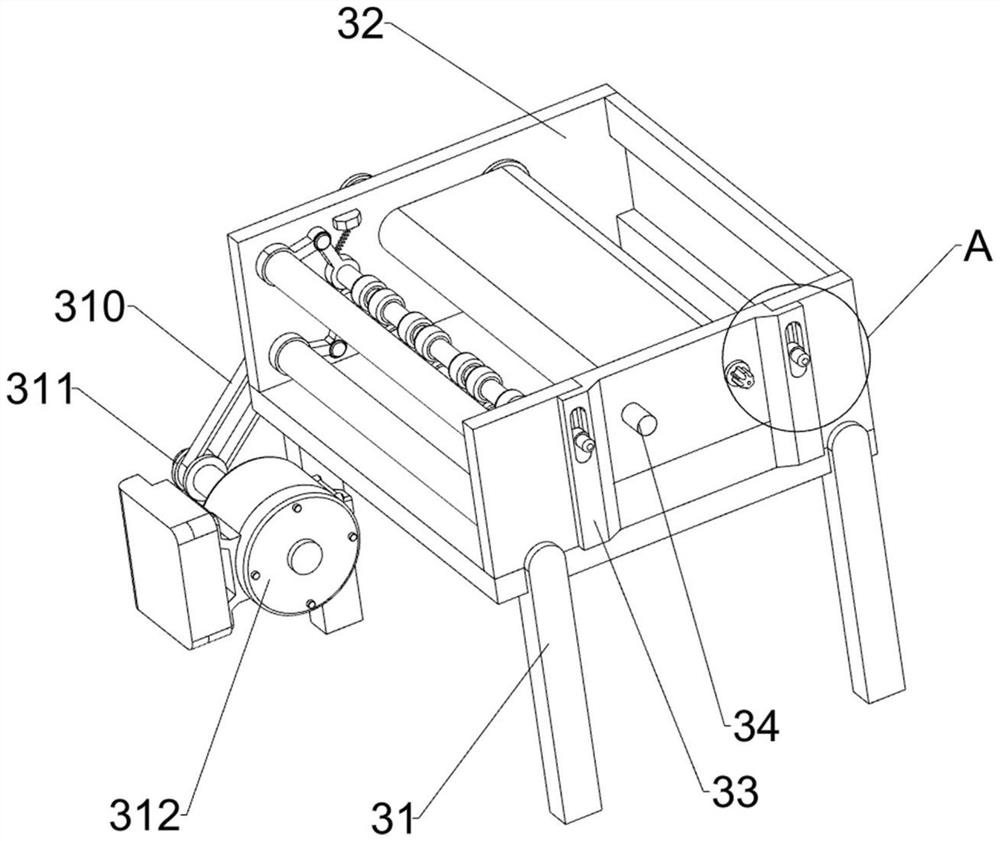
[0082] A surface fine grinding device based on PS plate production, such as figure 1 , figure 2 , image 3 and Figure 4 As shown, it includes a bottom plate 1, a feeding mechanism 2, a grinding mechanism 3 and a pushing mechanism 4. The top right side of the bottom plate 1 is provided with a feeding mechanism 2, the middle part of the top side of the bottom plate 1 is provided with a grinding mechanism 3, and the feeding mechanism 2 is provided with a There is a driving mechanism4.

[0083] The feeding mechanism 2 includes a first support column 21, a first connecting rod 22, a moving limit rod 23, a first locking rod 24 and a fixed limit rod 25. A first support column 21, a first connecting rod 22 is arranged between the first supporting column 21 tops on the same side in the longitudinal direction, and a moving stop rod 23 is slidingly provided between the rear sides of the first connecting rod 22, and the first connecting rod The rear sides of the rods 22 are all slid...

Embodiment 2

[0088] On the basis of Example 1, such as figure 2 , Figure 5 , Figure 6 , Figure 7 and Figure 8 As shown, an auxiliary moving mechanism 5 is also included, and the auxiliary moving mechanism 5 includes a first fixed block 51, a groove cylinder 52, a bevel gear 53, a connecting block 54, a slide bar 55, a second spring 56 and a second fixed block 57, The first support column 21 front side middle part of the front side is provided with the first fixed block 51, and between the first fixed block 51, the grooved cylinder 52 is arranged in rotation, and the left side of the grooved cylinder 52 and the output shaft of the motor 312 are all provided with cones. The gear 53 and the bevel gear 53 are meshed with each other. The front side of the first fixed rod 42 is provided with a connecting block 54. The lower part of the left side of the connecting block 54 is provided with a second fixed block 57. The front side of the second fixed block 57 rotates and slides. Slide bar ...


PUM


Abstract

The invention relates to a polishing device, in particular to a surface fine polishing device based on PS plate production. The surface fine polishing device based on PS plate production is used for achieving the technical purposes of being capable of automatically feeding, fixing and polishing PS plates and good in polishing effect. The surface fine polishing device based on PS plate production comprises a bottom plate, a feeding mechanism, a polishing mechanism and a pushing mechanism, wherein the feeding mechanism is arranged on one side of the top of the bottom plate, the polishing mechanism is arranged in the middle of the top side of the bottom plate, and the pushing mechanism is arranged on the feeding mechanism. Through cooperation of the feeding mechanism, the polishing mechanism and the pushing mechanism, the PS plates can be automatically polished, the working efficiency of a user is improved, abrasive paper can be replaced by the user, and the polishing effect is good; and through an auxiliary moving mechanism, the PS plates can be automatically fed, and time and labor are saved.

Description

technical field [0001] The invention relates to a grinding device, in particular to a surface fine grinding device based on PS board production. Background technique [0002] PS sheet is a kind of organic sheet, which is mainly used in packaging, container equipment, daily decoration, general electrical appliances and construction industries. PS sheet is a kind of thermoplastic, which has the advantages of high transparency, excellent electrical insulation and high frequency Insulation, odorless, tasteless and non-toxic, so it is widely used by people. [0003] After the PS board is produced, its surface needs to be polished. According to the current technology, the PS board is usually polished manually with tools such as sandpaper, and people need to fix the position of the PS board by hand during grinding. It takes a lot of time and energy for people, which leads to low work efficiency, and the effect of manual grinding is not good, and it is easy to cause uneven grinding...

Claims


Application Information

Patent Timeline
Patent Type & Authority Applications(China)
IPC IPC(8): B24B7/30B24B41/00B24B41/04B24B47/20
CPCB24B7/30B24B41/005B24B41/04B24B47/20Y02P70/10
Inventor 胡东鄢乐印
Owner 南丰县致诚科技有限公司
Learn More