Flat plate die-cutting machine with die-cutting size convenient to adjust

A die-cutting machine and size technology, applied in metal processing and other directions, can solve the problem of inconvenient adjustment of die-cutting size, and achieve the effect of suitable promotion and use, maintaining stability, and maintaining the stability of cutting tools.

Inactive Publication Date: 2021-04-30
杭州心杨科技有限公司
View PDF0 Cites 1 Cited by
  • Summary
  • Abstract
  • Description
  • Claims
  • Application Information

AI Technical Summary

Problems solved by technology

[0004] The invention proposes a flat die-cutting machine that is convenient for adjusting the die-cutting size, which solves the problem of inconvenient adjustment of the die-cutting size of the existing die-cutting machine

Method used


Image

  • Flat plate die-cutting machine with die-cutting size convenient to adjust
  • Flat plate die-cutting machine with die-cutting size convenient to adjust
  • Flat plate die-cutting machine with die-cutting size convenient to adjust

Examples


Embodiment 1

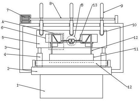
[0031] refer to figure 1 and Figure 4 , a flat die-cutting machine for easy adjustment of die-cutting size, including a base 1, a workbench 2 is fixedly installed on the top of the base 1, and a plurality of feeding rollers 12 with the same structure are installed on the top of the workbench 2 through brackets rotating at equal intervals , between the two sides of the workbench 2, a mounting frame 3 with a U-shaped overall structure is fixedly installed, and a driving motor 7 is fixedly mounted on one side of the top of the mounting frame 3, and the output shaft of the driving motor 7 is horizontally arranged, and is fixedly installed There is a rotating rod 8, and the body of the rotating rod 8 is fixedly connected with multiple groups of equally spaced push plates 9, and the two pushing plates 9 of the same group are symmetrically distributed with respect to the rotating rod 8, and a top plate 5 is arranged above the workbench 2. , and the top plate 5 is located below the ...

Embodiment 2

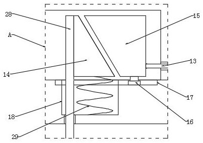
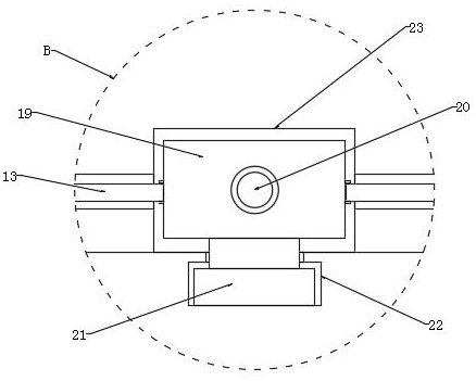
[0035] refer to Figure 1-7 , the adjustment mechanism includes an adjustment rod 20, a first movable groove 6, a hinged rod 13, a movable block 14, an abutment plate 15, a second movable groove 18, a movable plate 19, a third movable groove 23, a riser 28 and a return spring 29 , the inside of the top plate 5 is provided with a third movable groove 23, two symmetrically distributed first movable grooves 6 and two symmetrically distributed second movable grooves 18, the third movable groove 23 is located in the middle of the top plate 5, and The two second movable grooves 18 and the two first movable grooves 6 are all symmetrical about the third movable groove 23, and the second movable grooves 18 are located below the first movable groove 6 and communicate with each other, and slide in the third movable groove 23 Two movable plates 19 that are symmetrically distributed are installed, and movable blocks 14 and abutment plates 15 are slidably installed in the first movable groo...


PUM


Abstract

The invention discloses a flat plate die-cutting machine with the die-cutting size convenient to adjust, and relates to the field of die-cutting machines. In order to solve the problem that the die-cutting size of an existing die-cutting machine is inconvenient to adjust, the following scheme is provided: the flat plate die-cutting machine comprises a base, and a workbench is fixedly installed at the top end of the base. A plurality of feeding rollers of the same structure are rotatably mounted at the top end of the workbench at equal intervals through supports, a mounting frame with a U-shaped overall structure is fixedly mounted between the two sides of the workbench, a driving motor is fixedly mounted on one side of the top end of the mounting frame, an output shaft of the driving motor is transversely arranged, and a rotating rod is fixedly mounted. The flat plate die cutting device is novel in structure, can perform regular die cutting operation, and can also adjust the distance between a die cutting blade and the workbench rapidly and effectively, thereby being suitable for cutting, stamping and indentation operation of different thicknesses. Meanwhile, the stability of the die cutting blade can be kept, and the die cutting device is suitable for application and popularization.

Description

technical field [0001] The invention relates to the field of die-cutting machines, in particular to a flat die-cutting machine which is convenient for adjusting the die-cutting size. Background technique [0002] Die-cutting machine is also called beer machine, cutting machine, CNC punching machine, mainly used for die-cutting, indentation and bronzing of some non-metallic materials, stickers, EVA, double-sided tape, electronics, mobile phone rubber pads, etc. Operation, lamination, automatic waste discharge, die cutting machine uses steel knife, metal mold, steel wire, exerts a certain pressure through the embossing plate, and cuts the printed matter or cardboard into a certain shape. It is an important equipment for post-press packaging processing and molding. The working principle of the die-cutting machine is to use a die-cutting knife, a steel knife, a metal mold, and a steel wire to apply a certain pressure through the embossing plate to cut the printed matter or card...

Claims


Application Information

Patent Timeline
Patent Type & Authority Applications(China)
IPC IPC(8): B26D7/26B26F1/44B26F1/38B26D7/06
CPCB26D7/06B26D7/2614B26D7/2628B26F1/38B26F1/44
Inventor 不公告发明人
Owner 杭州心杨科技有限公司
Why Eureka
Try Eureka