Device for measuring steel wire position of slicing machine

A slicer and steel wire technology, applied in the direction of measuring devices, mechanical measuring devices, mechanical devices, etc., can solve the problems of increased product scrap rate, economic loss, and inability to determine whether it meets the best cutting state, etc.

Active Publication Date: 2021-09-10
宁夏中欣晶圆半导体科技有限公司
View PDF28 Cites 0 Cited by
  • Summary
  • Abstract
  • Description
  • Claims
  • Application Information

AI Technical Summary

Problems solved by technology

At this stage, relying on the operating experience of the staff to adjust the position of the guide wheel, it is impossible to determine whether it meets th

Method used


Image

  • Device for measuring steel wire position of slicing machine
  • Device for measuring steel wire position of slicing machine
  • Device for measuring steel wire position of slicing machine

Examples


Embodiment

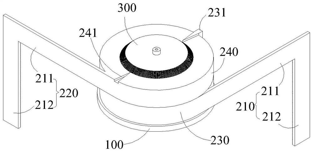
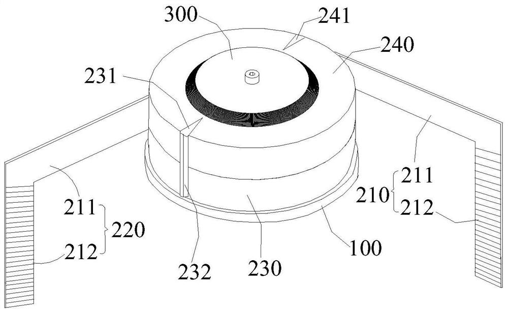
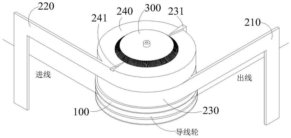
[0041] (1) Measure the angle between the incoming and outgoing wires of the steel wire and adjust the angle between the incoming and outgoing wires to the best state, please refer to Figure 1 to Figure 8 , the specific operation is: the device is installed on the guide wheel, so that the vertical arm 212 of the first measuring arm 210 and the vertical arm 212 of the second measuring arm 220 are respectively attached to the outgoing line and the incoming line of the steel wire, from the dial 300 Read the scales pointed to by the first indicator needle 231 and the second indicator needle 241 respectively. If the absolute value of the scale difference between the indicator needles is 180°, the angle between the incoming line and the outgoing line is 90°. If indicated If the angle between the needles is not 180°, you need to adjust the position of the guide wheel until the angle between the first indicator needle 231 and the second indicator needle 241 is 180°, then the angle betw...


PUM


Abstract

A device for measuring the position of a steel wire of a slicing machine belongs to the technical field of measurement of the position of the steel wire of the slicing machine and comprises a fixing seat and a measuring assembly, the measuring assembly comprises a first measuring arm, a second measuring arm, a first measuring arm fixing seat and a second measuring arm fixing seat, and the first measuring arm comprises a horizontal arm and a vertical arm. When the device is installed on a wire guide wheel, the vertical arm of the first measuring arm and the vertical arm of the second measuring arm are just close to an inlet wire and an outlet wire of a steel wire respectively, and when the included angle between the horizontal arm of the first measuring arm and the horizontal arm of the second measuring arm is 90 degrees, the included angle between the inlet wire and the outlet wire of the steel wire is 90 degrees. And if the measured included angle between the inlet wire and the outlet wire of the steel wire is not 90 degrees, the position of the wire guide wheel is adjusted until the included angle between the inlet wire and the outlet wire of the steel wire is 90 degrees. The device is easy and convenient to install, convenient to disassemble, easy to operate and convenient to carry.

Description

technical field [0001] The invention belongs to the technical field of line level measurement of slicer steel wires, in particular to a device for measuring the line level of slicer steel wires. Background technique [0002] At present, the silicon rod slicing machine on the market relies on the high-speed rotation of the guide wheel with the wire mesh, and the rotation of the main roller shaft drives the steel wire to perform high-speed reciprocating motion. When the silicon rod slowly approaches and contacts the high-speed moving steel wire, the steel wire and The silicon rod is rubbed to achieve cutting. [0003] As attached to the manual Figure 8 As shown, only when the position of guide wheel 1 and guide wheel 2 is correct can the angle between the wire entering and exiting the guide wheel be 90°, and when the angle between the wire entering and exiting the guide wheel is 90°, it is the best The best cutting state, in order to ensure the best cutting state, it is nece...

Claims


Application Information

Patent Timeline
IPC IPC(8): G01B5/24G01B5/00B65H57/14
CPCG01B5/24G01B5/0002B65H57/14
Inventor 刘波历莉赵延祥程博王忠保
Owner 宁夏中欣晶圆半导体科技有限公司
Why Eureka
Try Eureka