Melt-blown cloth production die cutting machine with adsorption transfer structure

A technology of transfer structure and die cutting machine, which is applied in the cutting of textile materials, textile and paper making, metal processing, etc., and can solve problems such as danger, damage to melt blown cloth, unfavorable melt blown cloth production and sterilization treatment, etc.

Pending Publication Date: 2022-04-12
肖军强
View PDF2 Cites 0 Cited by
  • Summary
  • Abstract
  • Description
  • Claims
  • Application Information

AI Technical Summary

Problems solved by technology

[0006] The purpose of the present invention is to provide a die-cutting machine for the production of melt-blown cloth with an adsorption transfer structure, to solve the existing die-cutting machines on the market proposed by the above-mentioned background technology, when cutting soft materials, especially It is aimed at the melt-blown cloth. Because the texture of the melt-blown cloth is soft, it is inconvenient to take and transfer the formed melt-blown cloth after die-cutting the melt-blown cloth. The damage or contamination of the cloth is not conducive to the subsequent production and sterilization of the melt-blown cloth, and after the die-cutting of the melt-blown cloth, there will be more or less cutting chips remaining on the edge of the formed melt-blown cloth. Cleaning will affect the use of subsequent melt-blown cloth, and the die-cutting knife is exposed outside. During the operation or cleaning of the die-cutting machine, dangerous situations are prone to occur.

Method used


Image

  • Melt-blown cloth production die cutting machine with adsorption transfer structure
  • Melt-blown cloth production die cutting machine with adsorption transfer structure
  • Melt-blown cloth production die cutting machine with adsorption transfer structure

Examples


Embodiment Construction

[0029] Based on the embodiments of the present invention, all other embodiments obtained by persons of ordinary skill in the art without making creative efforts belong to the protection scope of the present invention.

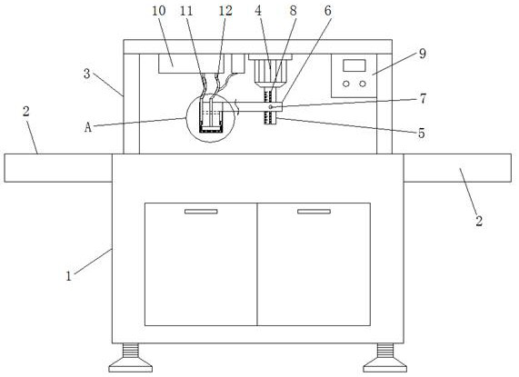
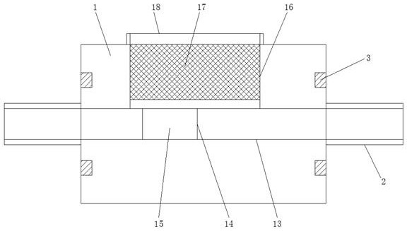
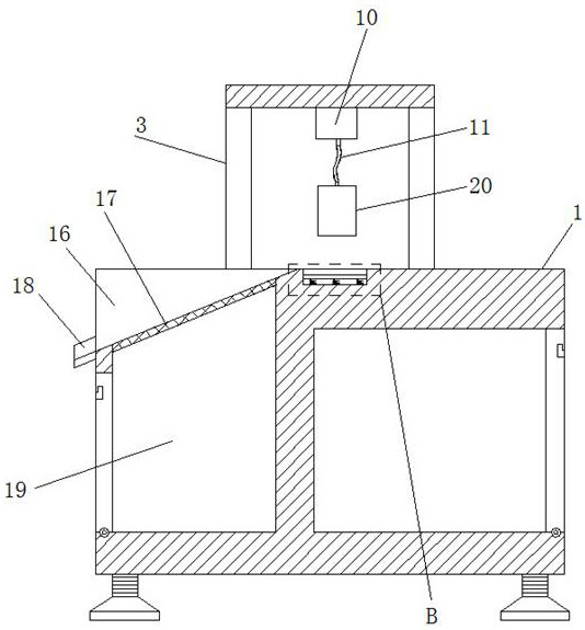
[0030] see Figure 1-9, the present invention provides a technical solution: a die-cutting machine for melt-blown cloth production with an adsorption transfer structure, including a die-cutting machine body 1, a guide frame 2, a bracket 3, a stepping motor 4, a rotating rod 5, and a support sleeve 6. Top tightening knob 7, embossed groove 8, control box 9, air pump structure 10, first air guide pipe 11, second air guide pipe 12, guide groove 13, installation groove 14, pallet 15, feeding area 16, protection Net 17, chute 18, slag collecting area 19, die cutting frame 20, spring 21, first air guiding chamber 22, second air guiding chamber 23, pushing structure 24, die cutting knife 25, storage bin 26, communication cavity 27, Air vent 28, sealing ring 29, screw...


PUM


Abstract

The invention discloses a melt-blown cloth production die cutting machine with an adsorption transfer structure, which comprises a die cutting machine body, guide frames, a support, a stepping motor, a rotating rod, a control box, an air pump structure, a sealing ring and a screw, the guide frames are arranged on the two sides of the die cutting machine body, and the support is welded to the top end of the die cutting machine body; a stepping motor is fixed to the middle of the inner side of the upper end of the support, meanwhile, the lower end of the stepping motor is connected with a rotating rod, the lower portion of the rotating rod is sleeved with a supporting sleeve, a slag collecting area with a door plate is arranged below the protective net, and a chute is welded to the portion, at the lower end of the rear side of the protective net, of the die cutting machine body. According to the die cutting machine with the adsorption transfer structure for melt-blown cloth production, formed melt-blown cloth can be quickly transferred, direct contact with the melt-blown cloth is not needed, intactness of the melt-blown cloth is facilitated, in the process of taking out the melt-blown cloth, the melt-blown cloth can be blown, and scraps on the cutting edge of the melt-blown cloth can be removed.

Description

technical field [0001] The invention relates to the technical field of a die-cutting machine for producing melt-blown cloth, in particular to a die-cutting machine for producing melt-blown cloth with an adsorption transfer structure. Background technique [0002] Melt-blown cloth is an indispensable core material for making masks. It mainly plays the role of filtration and absorption. The quality of the mask determines the effect of epidemic prevention against germs. The sprayed flannel cloth is in it. For example, the comparative document application number: CN201711072599.X, authorized announcement number : A kind of sporting goods outer skin die-cutting machine of CN107877611B, its structure comprises die-cutting machine, fixed pillar, controller, waste material inlet, cleaning door cabinet, bottom supporting foot, waste material collection box and forms, sporting goods outer skin die-cutting machine of the present invention , the body of the die-cutting machine is equipp...

Claims


Application Information

Patent Timeline
Patent Type & Authority Applications(China)
IPC IPC(8): B26F1/38B26D5/08B26D7/18B26D7/22B26D7/32B26D7/00D06H7/00
Inventor 肖军强
Owner 肖军强
Why Eureka
Try Eureka