Household dry wood convenient splitting device
A convenient and dry wood technology, used in wood splitting devices, wood processing appliances, manufacturing tools, etc., can solve problems such as incomplete combustion, difficulty in keeping the same size of dry wood, and waste of dry wood.
- Summary
- Abstract
- Description
- Claims
- Application Information
AI Technical Summary
Problems solved by technology
Method used
Image
Examples
Embodiment 1
[0071] A kind of household dry firewood convenient splitting device, such as figure 1 As shown, it includes a mounting base 1 , a placing mechanism 2 and a cutting mechanism 3 , the mounting base 1 is provided with a placing mechanism 2 , and the placing mechanism 2 is provided with a cutting mechanism 3 .
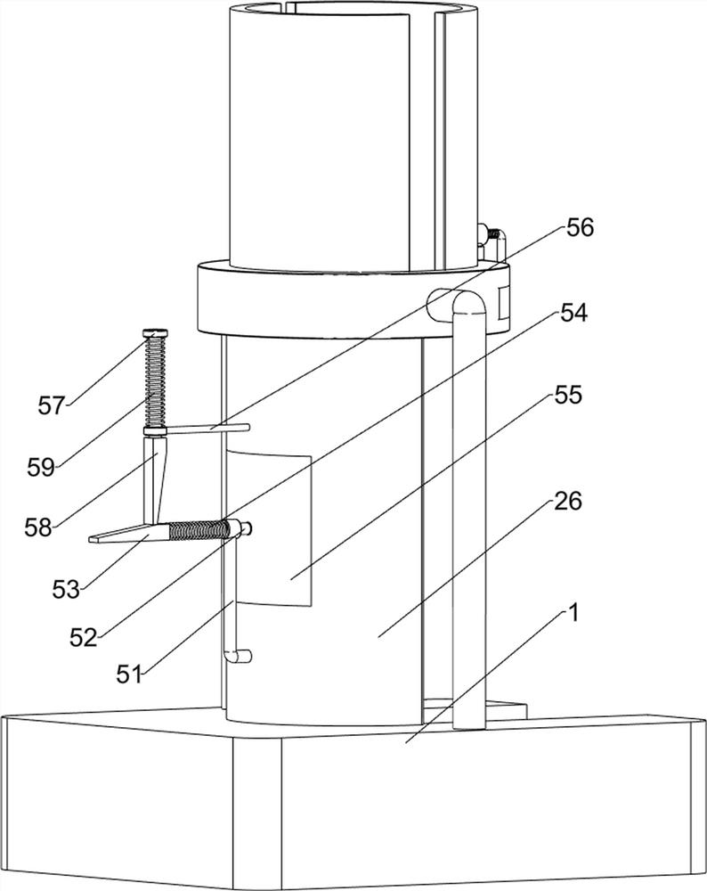
[0072] Such as figure 2 with image 3As shown, the placement mechanism 2 includes a first mounting column 21, a mounting table 22, a cutter 23, a block 24, a first baffle 25, a second baffle 26, a second mounting column 27, a first guide sleeve 28, The first special-shaped rod 29, the stop block 210 and the first spring 211, the first mounting column 21 is arranged on the front and rear sides of the mounting seat 1 top, and the mounting platform 22 is connected between the first mounting column 21 tops, and the mounting platform 22 The sliding type is provided with a cutter 23, the sliding type on the right side of the mounting table 22 is provided with a stopper 24, th...
Embodiment 2
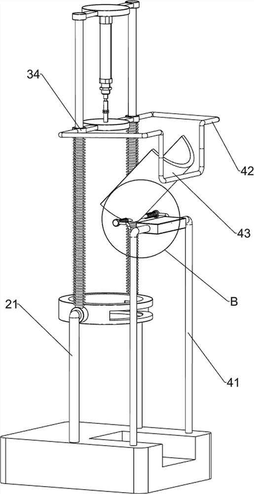
[0076] On the basis of Example 1, such as Figure 5 with Image 6 As shown, a feed mechanism 4 is also included, and the feed mechanism 4 includes a fourth mounting column 41, a second special-shaped rod 42, a discharge plate 43, a supporting plate 44, a third special-shaped rod 45, a rotating shaft 46 and a third spring 47, The right side of the top of the mounting base 1 is symmetrically provided with a fourth mounting column 41, the outside of the push plate 34 is provided with a second special-shaped rod 42, the top of the fourth mounting column 41 is connected with a supporting plate 44, and the left upper part of the fourth mounting column 41 Both are provided with a third special-shaped rod 45, and a rotating shaft 46 is rotatably connected between the third special-shaped rods 45. The middle part of the rotating shaft 46 is provided with a discharge plate 43, and the discharge plate 43 cooperates with the second special-shaped rod 42. The front and rear of the discharg...
PUM
 Abstract
Description
Claims
Application Information
 - R&D
- Intellectual Property
- Life Sciences
- Materials
- Tech Scout
- Unparalleled Data Quality
- Higher Quality Content
- 60% Fewer Hallucinations
Browse by: Latest US Patents, China's latest patents, Technical Efficacy Thesaurus, Application Domain, Technology Topic, Popular Technical Reports.
© 2025 PatSnap. All rights reserved.Legal|Privacy policy|Modern Slavery Act Transparency Statement|Sitemap|About US| Contact US: help@patsnap.com


