
A large gas turbine intake system cleaning equipment

An air intake system and gas turbine technology, applied in fuel air filters, charging systems, mechanical equipment, etc., can solve the problems of uneven purging, long operation time, dust pollution, etc., saving labor, blowing The effect of even sweeping and stable air pressure

Active Publication Date: 2019-11-29
LIANNUOOU MACHINERY TECHOLOGY JIANGSU CO LTD
View PDF5 Cites 0 Cited by
  • Summary
  • Abstract
  • Description
  • Claims
  • Application Information

AI Technical Summary

Problems solved by technology

[0002] The cleaning device used in the gas engine air intake system used in the prior art usually has uneven blowing, and the filter element needs to be disassembled to clean and blow off, the efficiency is very low, and when there are many filter elements, the operation time is too long
And it is easy to pollute the dust inside the filter element
Shutdown required for purging

Method used


Image

  • A large gas turbine intake system cleaning equipment

Examples


Embodiment 1

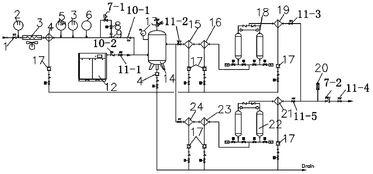
[0014] Embodiment one: if figure 1 As shown, the present invention includes a twin-screw air compressor 12, the twin-screw air compressor 12 is connected to a first air storage tank 14, and the other end of the first air storage tank 14 is connected to a solenoid valve through a first one-way valve 10-1 8, the twin-screw air compressor 12 is provided with a second one-way valve 10-2 and a first valve 11-1, and the electromagnetic valve 8 is connected with the first decompression valve 7-1 and the first one-way valve 10-1. The pressure switch 6, the thermometer 2, and the temperature switch 5 are connected in series. The other end of the thermometer 2 is connected to the air-cooled air cooler 3 through the cyclone oil-water separator, and the other end of the air-cooled air cooler 3 is connected to the high temperature The valve 1 is connected; the first gas storage tank 14 is provided with a shockproof glycerin pressure gauge 13 and a safety valve, the first gas storage tank 1...


PUM


Abstract

The invention discloses cleaning equipment for air inlet systems of large gas turbines. The cleaning equipment comprises a double-screw air compressor, wherein the double-screw air compressor is connected with a first gas storage tank; one end of the first gas storage tank is connected with a solenoid valve by the aid of a one-way valve; the solenoid valve is connected with a pressure reducing valve, the one-way valve, a pressure switch, a thermometer and a temperature switch; the first gas storage tank is connected with a first primary filter by the aid of a lead; the first primary filter is connected with a first precision filter, a first non-heat-adsorption type drying machine, a second precision filter and a valve in series; the first primary filter is connected with a second gas storage tank in parallel; and the second gas storage tank is connected with a second primary filter, a third precision filter, a second non-heat-adsorption type drying machine and a valve in series. The cleaning equipment has the characteristics that back flushing is realized by the aid of tail gas produced by the gas turbines, meanwhile, instrument gas can be provided, when the unit is maintained, no tail gas is produced, but the compressor can work, and a stable gas source is provided.

Description

technical field [0001] The invention relates to the technical field of gas equipment, in particular to cleaning equipment for the intake system of a large gas turbine. Background technique [0002] The cleaning device used in the gas engine air intake system used in the prior art is usually uneven in blowing, and the filter elements need to be disassembled for cleaning and blowing, and the efficiency is very low. When there are many filter elements, the operating time is too long. And it is easy to pollute the dust inside the filter element. Shutdown is required for purging. Contents of the invention [0003] Purpose of the invention: In order to overcome the deficiencies in the prior art, the present invention provides a method of blowing back using the exhaust gas generated by the gas turbine, and at the same time can provide instrument gas. When the unit is overhauled, there is no exhaust gas, but the compressor can work, providing Large gas turbine intake system clea...

Claims


Application Information

Patent Timeline
Patent Type & Authority Patents(China)
IPC IPC(8): F02M35/08
CPCF02M35/086
Inventor 朱昌龙
Owner LIANNUOOU MACHINERY TECHOLOGY JIANGSU CO LTD
Learn More