
A convenient device for splitting dry firewood for household use

A convenient and dry wood technology, used in wood splitting devices, manufacturing tools, wood processing utensils, etc., can solve problems such as difficulty in keeping the same size of dry wood, waste of dry wood, incomplete combustion, etc., and achieve the effect of saving manpower

Active Publication Date: 2022-05-27
陈仪金
View PDF0 Cites 0 Cited by
  • Summary
  • Abstract
  • Description
  • Claims
  • Application Information

AI Technical Summary

Problems solved by technology

[0004] In order to overcome the disadvantages that the size of dry firewood cut manually is difficult to keep consistent, and the larger ones cannot be completely burned after being put into the stove, resulting in the waste of dry firewood, the technical problem of the present invention is: to provide a method that can automatically dry firewood. Split, the size of the split dry wood is the same, which can make it completely burnt. A convenient split device for household dry wood

Method used


Image

  • A convenient device for splitting dry firewood for household use
  • A convenient device for splitting dry firewood for household use
  • A convenient device for splitting dry firewood for household use

Examples


Embodiment 1

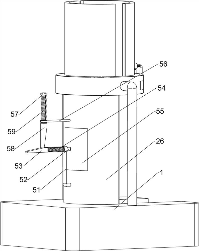
[0071] A convenient cutting device for household dry wood, such as figure 1 As shown, it includes a mounting base 1 , a placing mechanism 2 and a cutting mechanism 3 . The top of the mounting base 1 is provided with a placing mechanism 2 , and the placing mechanism 2 is provided with a cutting mechanism 3 .

[0072] like figure 2 and image 3As shown, the placement mechanism 2 includes a first installation column 21, an installation table 22, a cutter 23, a stopper 24, a first stopper 25, a second stopper 26, a second installation column 27, a first guide sleeve 28, The first special-shaped rod 29 , the limiting block 210 and the first spring 211 , the top of the mounting seat 1 is provided with a first mounting column 21 on the front and rear sides, and the top of the first mounting column 21 is connected with a mounting table 22 , and inside the mounting table 22 The sliding type is provided with a cutter 23, the right side of the mounting table 22 is slidingly provided w...

Embodiment 2

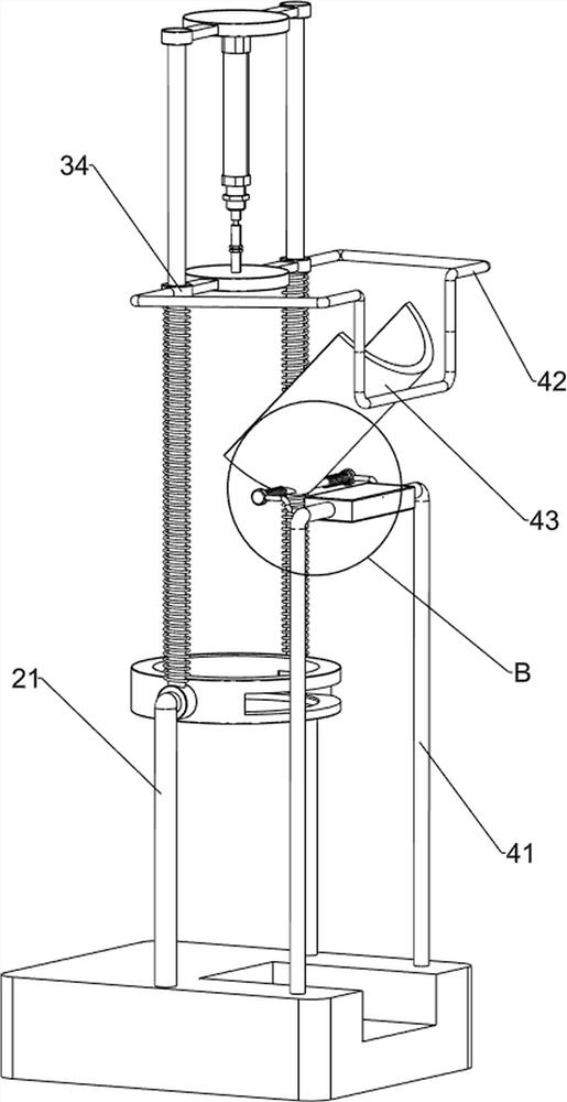
[0076] On the basis of Example 1, as Figure 5 and Image 6 As shown, it also includes a feeding mechanism 4, and the feeding mechanism 4 includes a fourth mounting column 41, a second special-shaped rod 42, a discharge plate 43, a support plate 44, a third special-shaped rod 45, a rotating shaft 46 and a third spring 47, A fourth mounting post 41 is symmetrically arranged on the right side of the top of the mounting seat 1 in front and back, a second special-shaped rod 42 is provided on the outer side of the push plate 34, a support plate 44 is connected between the top of the fourth mounting post 41, and the upper part of the left side of the fourth mounting post 41 Each is provided with a third special-shaped rod 45, a rotating shaft 46 is rotatably connected between the third special-shaped rod 45, and a discharging plate 43 is arranged in the middle of the rotating shaft 46, and the discharging plate 43 cooperates with the second special-shaped rod 42, and the discharging...


PUM


Abstract

The invention relates to a splitting device, in particular to a convenient splitting device for household dry wood. The technical problem of the present invention is: to provide a kind of dry firewood that can automatically cut dry firewood, and the dry firewood that cut open has the same size, and can make it burn completely the convenient household dry firewood splitting device. A device for conveniently cutting dry firewood for household use, comprising: a mounting base, a placement mechanism is provided on the top of the mounting base; and a cutting mechanism, a cutting mechanism is provided on the placement mechanism. Through the cooperation between the set placement mechanism and the cutting mechanism, the staff only need to put the dry wood in place, and can complete the work of cutting the dry firewood by controlling the operation of the cylinder; the staff have sufficient time through the set feeding mechanism Place new wood.

Description

technical field [0001] The invention relates to a cutting device, in particular to a convenient cutting device for household dry wood. Background technique [0002] In daily life in rural areas, dry wood is often put into the stove as fuel for cooking rice and water. However, after the dry wood is collected, it is usually thick and easy to block after being put into the stove, so it cannot be used for cooking. It is completely burned, so it needs to be cut open. At present, after the dry wood is put away, the dry wood is manually chopped with a splitter to cut it open. However, the size of the dry wood cut by this method is difficult to keep the same. After the large ones are put into the stove, they still cannot be completely burned, resulting in waste of dry wood. [0003] Therefore, it is necessary to design a convenient and convenient cutting device for household dry wood that can automatically cut the dry wood, the size of the cut dry wood is the same, and can make it ...

Claims


Application Information

Patent Timeline
Patent Type & Authority Patents(China)
IPC IPC(8): B27L7/06
CPCB27L7/06
Inventor 陈仪金
Owner 陈仪金
Learn More