Locomotive brake resistor fault intelligent monitoring method

A technology of braking resistance and intelligent monitoring, applied in the direction of brakes, motor vehicles, brake components, etc., can solve problems such as unsolved problems, and achieve the effect of small changes

Active Publication Date: 2021-04-30
SHIDAI ELECTRIC FACTORY ZHUZHOU ELECTRIC LOCOMOTIVES INST MIN OF RAILWAYS
View PDF14 Cites 0 Cited by
  • Summary
  • Abstract
  • Description
  • Claims
  • Application Information

AI Technical Summary

Problems solved by technology

[0009] Through the analysis of the above patent documents, we found that these patents are all related to the control of braking resistors, and many of them are based on the research on temperature control, and some improved technical solutions have also been proposed, but these technical solutions still exist Some problems still have not solved some practical problems, resulting in many unexpected problems and failures in practical applications, so it is still necessary to do further research on this

Method used


Image

  • Locomotive brake resistor fault intelligent monitoring method
  • Locomotive brake resistor fault intelligent monitoring method
  • Locomotive brake resistor fault intelligent monitoring method

Examples


Embodiment 1

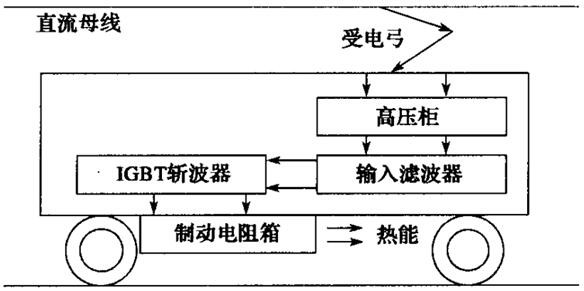
[0037] The working principle of the conventional locomotive braking resistor is attached figure 1 As shown; when the vehicle starts to brake with the braking resistor, the train will turn on the IGBT overvoltage chopping, and use the locomotive braking resistor to consume the regenerative energy of the IGBT chopping; and then use the fan to dissipate the heat of the locomotive braking resistor into the air; However, as the regenerative energy is dissipated on the braking resistor in the form of heat energy, the temperature of the resistor will gradually rise. It is necessary to monitor the braking resistor of the locomotive in real time to prevent the temperature of the braking resistor of the local locomotive from rising too fast, resulting in failure. Otherwise, it will seriously affect the safe operation of the vehicle traction system.

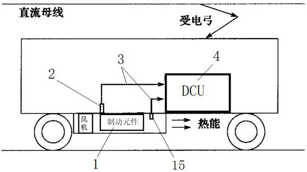
[0038] In order to obtain accurate braking resistor temperature, the present invention arranges a temperature sensor 2 in the body of the ...

Embodiment 2

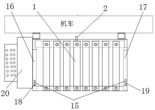
[0052] The principle of the second embodiment is basically the same as that of the first embodiment, except that the specific structure and processing methods are different; an intelligent monitoring method for the failure of the braking resistor of the locomotive, through the braking resistor on the body surface of the braking resistor of the locomotive Install a temperature sensor, attach the temperature sensor to the body surface of the braking resistor, directly collect the temperature value on the surface of the braking resistor element, convert the collected temperature value into a temperature electrical signal, and send it to the traction control through the CAN bus The unit (DCU) performs intelligent identification and monitoring. At the same time, an air duct air temperature sensor is installed at the outlet or entrance of the ventilation duct of the braking resistor. The air temperature in the air duct is detected by the air duct air temperature sensor, and the detect...


PUM


Abstract

A locomotive brake resistor fault intelligent monitoring method comprises the steps that a temperature sensor is arranged in a brake resistor element body or on the surface or around the surface of the brake resistor element body of a locomotive brake resistor, temperature signals on the brake resistor element are collected, and meanwhile an air duct air parameter detection sensor is arranged at an air duct opening of an air supply inlet or an air supply outlet of the locomotive brake resistor; air parameter information in an air duct of the locomotive brake resistor is collected through the air duct air parameter detection sensor, temperature signals and the air parameter information are sent to a traction control unit through a CAN bus to be intelligently recognized and monitored, and the condition of the locomotive brake resistor is determined through intelligent recognition of the traction control unit. Temperature signals and air parameter information are obtained by detecting the brake resistor element, the running condition of the locomotive brake resistor is intelligently recognized and judged through the temperature signals and the air parameter information, the running safety of the locomotive brake resistor is effectively protected, and the method is suitable for application and popularization of various locomotive brake resistors.

Description

technical field [0001] The invention relates to a component monitoring method of a locomotive brake system of an electric locomotive, in particular to an intelligent monitoring method for a brake resistor failure of a locomotive; the intelligent monitoring method for a brake resistor failure of a locomotive and the grounding resistance can effectively reduce the The invention relates to the occurrence of a resistance fault; it belongs to the technical field of electric locomotive manufacturing. Background technique [0002] At present, most electric locomotives use resistance braking. Using resistance braking, the original traction motor that drives the wheelset is converted into a generator. The inertia of the train is used to drive the rotor of the motor to rotate to generate electricity, thereby generating reverse torque and consuming the train. Kinetic energy, to achieve the purpose of braking. The electric current from the motor passes through specially set resistance ...

Claims


Application Information

Patent Timeline
Patent Type & Authority Applications(China)
IPC IPC(8): B60T17/22B60L7/02
CPCB60T17/228B60L7/02B60L2200/26
Inventor 肖宁吴志云
Owner SHIDAI ELECTRIC FACTORY ZHUZHOU ELECTRIC LOCOMOTIVES INST MIN OF RAILWAYS
Why Eureka
Try Eureka