
Efficient chip removal system for plasma rock breaking

A plasma and rock-breaking technology, applied in construction and other directions, can solve the problems of reducing rock-breaking efficiency, unable to achieve high-speed rock-breaking, etc., and achieve the effects of improving drilling efficiency, efficient chip removal, and simple drill bit structure

Inactive Publication Date: 2021-04-30
CHINA UNIV OF PETROLEUM (EAST CHINA)
View PDF0 Cites 2 Cited by
  • Summary
  • Abstract
  • Description
  • Claims
  • Application Information

AI Technical Summary

Problems solved by technology

Different from the conventional rotary mechanical drilling method, the rock debris produced by this technology is molten magma, while the conventional mud circulation rock carrying system will directly cool the magma, making the magma recondense at the bottom of the wellbore, which greatly reduces the Rock-breaking efficiency, unable to achieve high-speed rock-breaking

Method used


Image

  • Efficient chip removal system for plasma rock breaking

Examples


Embodiment Construction

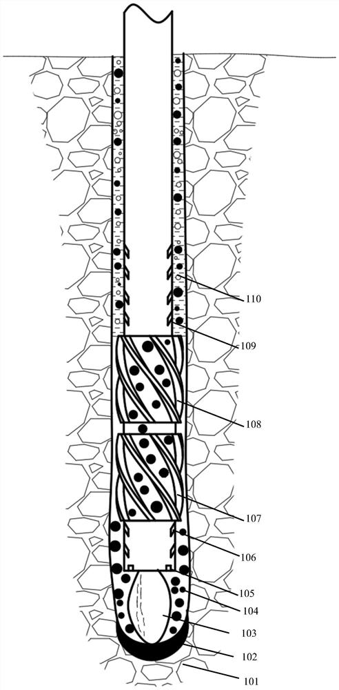
[0008] Such as figure 1 As shown, in the process of plasma rock breaking, the end of the plasma drill bit ejects a high-temperature and high-speed plasma arc 103, the high-temperature plasma arc 103 melts the formation 101 in the working area, and forms a molten magma pool 102 at the bottom of the well; There are multiple high-pressure gas nozzles 105, and the high-pressure gas nozzles 105 eject high-pressure gas intermittently, and the high-pressure gas is directly injected onto the magma pool 102, and the magma pool 102 is impacted into molten rock particles 104; multiple rising gas nozzles 106 are distributed on the drill bit , the outlet of the rising gas spout 106 is upward, and the rising gas spout 106 continuously ejects upward high-speed gas; the upward high-velocity gas blows the rock melting particles 104 upwards; at the high-pressure gas spout 105, the intermittent high-pressure gas and the rising gas spout 106 are sprayed Under the action of continuous high-pressur...


PUM


Abstract

The invention belongs to the field of petroleum engineering, and particularly relates to an efficient chip removal system for plasma rock breaking. In the plasma rock breaking process, no liquid exists in a plasma operation area, high-pressure gas is intermittently sprayed to the front portion of a drill bit, and a molten magma pool is impacted into rock molten particles; gas spraying openings with upward nozzles are distributed in the front portion of the drill bit, and the rock molten particles are blown upwards; a plurality of spiral grooves are distributed in a plasma drill column above the nozzles, the spiral grooves do rotation motion, and a plasma rock breaking area at the bottom of a shaft and a foam liquid circulation area on the upper portion are sealed and separated; the multiple stages of spiral grooves work in parallel, and the separation effect is improved; the rock molten particles blown into the spiral grooves move upwards to enter the foam liquid circulation area under the rotation effect of the spiral grooves; and foam liquid in the foam liquid circulation area cools the rock molten particles, and rock particles are formed; and the rock particles are conveyed to the ground under the lifting effect of the foam liquid. By means of the system, efficient chip removal can be achieved, and the well drilling efficiency is improved.

Description

technical field [0001] The invention belongs to the field of petroleum engineering, and in particular relates to a high-efficiency debris removal system for plasma rock breaking. Background technique [0002] Plasma drilling technology is a cutting-edge high-efficiency drilling technology, which uses high-temperature plasma to melt and gasify rocks to achieve rock fragmentation. Different from the conventional rotary mechanical drilling method, the rock debris produced by this technology is molten magma, while the conventional mud circulation rock carrying system will directly cool the magma, making the magma recondense at the bottom of the wellbore, greatly reducing the Rock-breaking efficiency cannot achieve high-speed rock-breaking. Therefore, it is of great significance to develop a high-efficiency debris removal system suitable for plasma rock breaking to promote the development of this technology. Contents of the invention [0003] At present, there is no efficient...

Claims


Application Information

Patent Timeline
Patent Type & Authority Applications(China)
IPC IPC(8): E21B21/01E21B21/16
CPCE21B21/01E21B21/16
Inventor 刘永红孙强韩延聪朱业俊刘鹏沈志萍马驰赵莅龙
Owner CHINA UNIV OF PETROLEUM (EAST CHINA)
Learn More