Electron beam exposure machine and focusing method and device

An electron beam exposure machine and electron beam emission technology, applied in the semiconductor field, can solve problems such as affecting the process results of electron beams and inaccurate focusing

Pending Publication Date: 2021-04-30
INST OF MICROELECTRONICS CHINESE ACAD OF SCI
View PDF3 Cites 3 Cited by
  • Summary
  • Abstract
  • Description
  • Claims
  • Application Information

AI Technical Summary

Problems solved by technology

[0003] At present, the focus adjustment method of the electron beam exposure machine is to adjust the focus through the fiducial marks on the slide table, but the surface of the sample to be exposed, such as the wafer, may have ups and downs, which leads to the fact that the fiducial marks cannot fully represent the surface of the wafer. In the actual situation, inaccurate focusing occurs, which affects the process results of electron beam exposure

Method used


Image

  • Electron beam exposure machine and focusing method and device
  • Electron beam exposure machine and focusing method and device
  • Electron beam exposure machine and focusing method and device

Examples


Embodiment Construction

[0024] Hereinafter, embodiments of the present disclosure will be described with reference to the drawings. It should be understood, however, that these descriptions are exemplary only, and are not intended to limit the scope of the present disclosure. Also, in the following description, descriptions of well-known structures and techniques are omitted to avoid unnecessarily obscuring the concepts of the present disclosure.

[0025] Various structural schematic diagrams according to embodiments of the present disclosure are shown in the accompanying drawings. The figures are not drawn to scale, with certain details exaggerated and possibly omitted for clarity of presentation. The shapes of the various regions and layers shown in the figure, as well as their relative sizes and positional relationships are only exemplary, and may deviate due to manufacturing tolerances or technical limitations in practice, and those skilled in the art will Regions / layers with different shapes, ...


PUM


Abstract

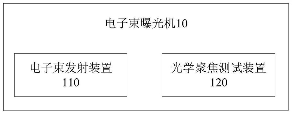
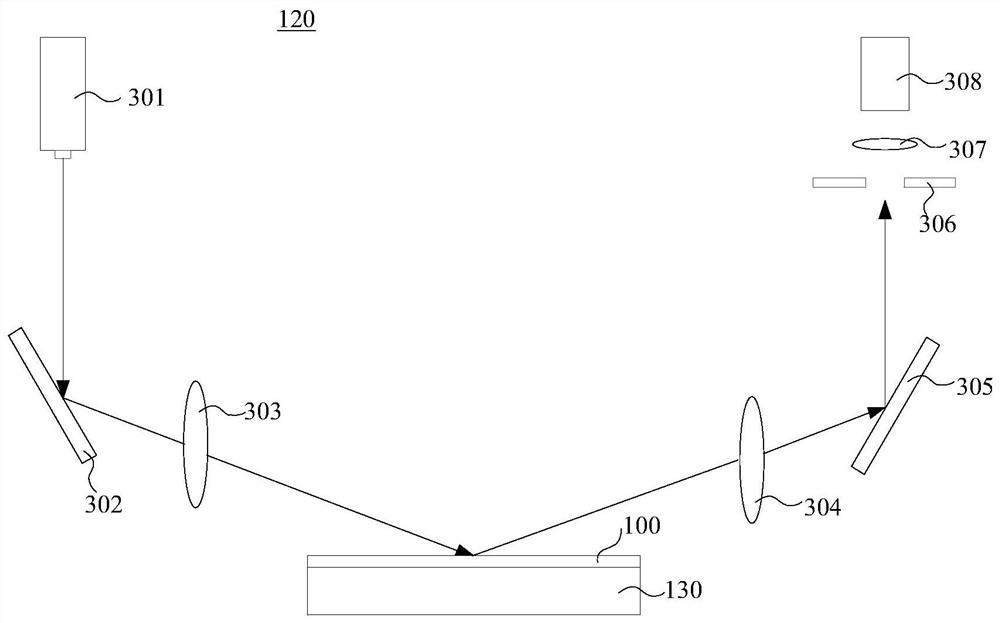
The invention discloses an electron beam exposure machine and a focusing method and device, and the method comprises the steps: enabling detection light to irradiate a current exposure unit of a to-be-exposed sample through additionally arranging an optical focusing testing device, collecting a reflected light image corresponding to the current exposure unit, and based on the reflected light image corresponding to the current exposure unit, obtaining the position information of the current exposure unit, and adjusting the focus position of the electron beam exposure of the current exposure unit according to the position information. Therefore, the focusing accuracy of the electron beam exposure machine can be effectively improved, the beam spot size is reduced, and the resolution of electron beam exposure is improved.

Description

technical field [0001] The invention relates to the technical field of semiconductors, in particular to an electron beam exposure machine, a focusing method and a device. Background technique [0002] Similar to optical exposure, the electron beam exposure process also has the concept of depth of field. When the electron beam is exposed, it needs to pass through the focusing lens system to focus the electron beam on a point for direct writing exposure on the photoresist. Therefore, the focusing effect will directly affect the beam spot size of the electron beam, and the beam spot size is a key parameter of the electron beam. The minimum resolution that the electron beam can achieve also depends on the beam spot size. Therefore, the focusing effect will directly affect the Electron beam process results. Before the electron beam exposure, it is necessary to determine the optimal focal length of the exposure, so that the electron beam can be focused on the wafer surface and t...

Claims


Application Information

Patent Timeline
Patent Type & Authority Applications(China)
IPC IPC(8): G03F7/20G03F9/00
CPCG03F7/2059G03F7/7085G03F9/7026
Inventor 贺晓彬李亭亭唐波刘金彪李俊峰杨涛
Owner INST OF MICROELECTRONICS CHINESE ACAD OF SCI
Why Eureka
Try Eureka