High-efficiency wafer box conveying device of wet cleaning equipment

A technology of wet cleaning and conveying device, applied in the direction of conveyor objects, transportation and packaging, electrical components, etc., can solve the problems affecting wafer transfer efficiency, wafer fragmentation, cumbersome operation process, etc., to ensure integrity and stability, increase the utilization rate, and the effect of simple transmission process

Active Publication Date: 2021-04-30
ULTRON SEMICON (SHANGHAI) CO LTD
View PDF7 Cites 4 Cited by
  • Summary
  • Abstract
  • Description
  • Claims
  • Application Information

AI Technical Summary

Problems solved by technology

Setting up the transfer clamping mechanism will take up a lot of space, and the operation process is cumbersome, which affects the transfer efficiency of the wafer
[0004] The transfer process of the wafer requires a combination of various devices and accessories. Since it is installed on the wet process equipment, various undesirable stress concentration, vibration, shaking, Phenomena such as offset and deflection will have unexpected adverse effects on the wafer and lead to wafer fragmentation. Therefore, a high-stability clamping device for clamping in the robotic arm device module can achieve wafer product protection. Position monitoring is of great significance for the transfer of wafer products

Method used


Image

  • High-efficiency wafer box conveying device of wet cleaning equipment
  • High-efficiency wafer box conveying device of wet cleaning equipment
  • High-efficiency wafer box conveying device of wet cleaning equipment

Examples


Embodiment 2

[0071]The structure of the present embodiment is substantially identical to the structure of the first embodiment, and the wafer detector is increased, and the wafer detector includes detecting the cylinder 12 and the detection sensor 13, detecting the sensor 13, and the detection sensor 13. The detection cylinder 12 is disposed directly below the first horizontal placement plate 2 structure. The first wafer cartridge 1 is provided with a plurality of wafer card slots, and the adjacent wafer card grooves form a card slot gap, and the detecting sensor 13 includes a plurality of parallel setting detecting sensing sheets. A card slot gap is formed between the adjacent wafer card grooves, and the detecting sensor 13 includes a plurality of parallel setting detecting sensors 13, detecting the position of the sensing sheet to the position of the card slot gap. In the receiving mechanism, the sliding push is increased, the sliding push hand includes the sliding track 9 and the push arm 10,...

Embodiment 3

[0073]This embodiment provides a wafer loading delivery method, and its working process is as follows:

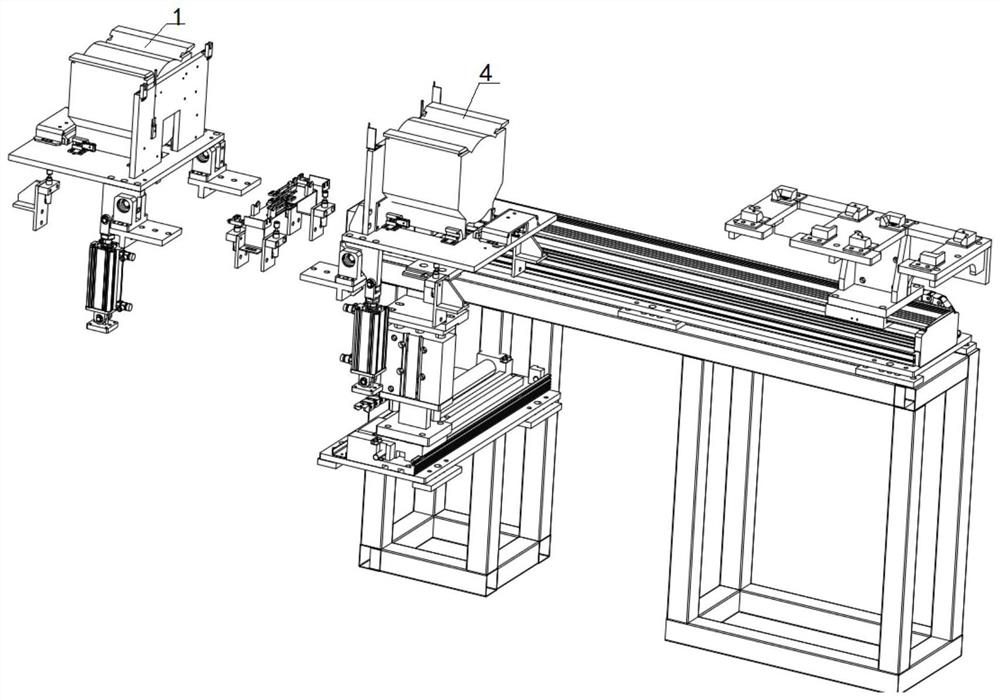
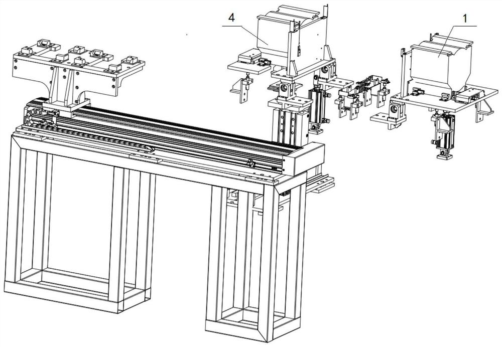
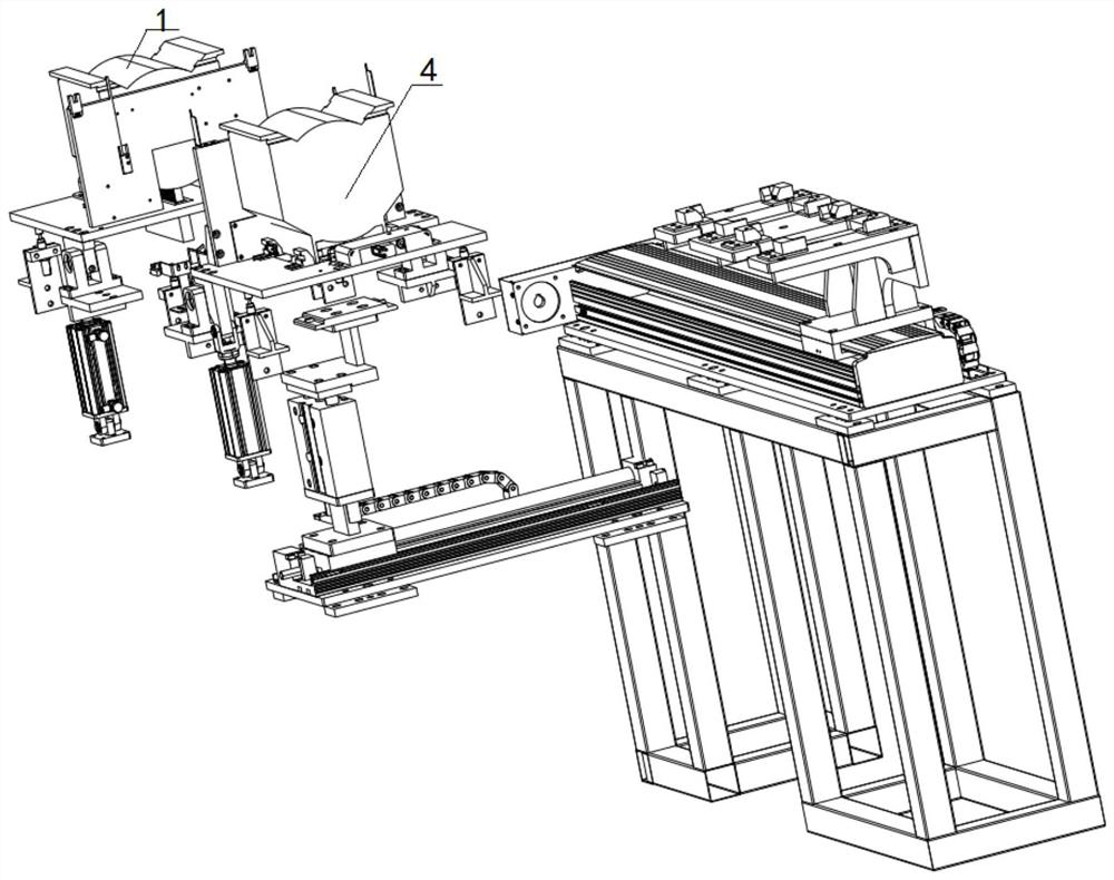
[0074]Step 1, the first horizontal place plate 2, the second horizontal place plate 5 is in a horizontal state in contact with the carrier 11, and the first vertical place plate 3, the second vertical place plate 6 is in a vertical state. The first wafer cassette 1 is loaded with a wafer, and the second wafer cassette 4 is an air load, and the sliding push is away from the first wafer box 1. The first limiting cylinder 21, the second resident cylinder 23 operates, and the first wafer cassette 1 is fixed to the first horizontal place plate 2, and the second wafer cartridge 4 is fixed to the second horizontal placing plate 5.

[0075]Step 2, the drive mechanism at the first placement is simultaneously operated with the drive mechanism at the second placement, and the first placement, the second placement is simultaneously rotated 90 degrees, the first wafer box 1, the second wafer The op...

Embodiment 4

[0082]This embodiment provides a wafer unloading delivery method, and its working process is as follows:

[0083]Step 6. The mechanical clamping mechanism takes the wafer box to the transfers orbit 24.

[0084]Step 1, after the two wafer casings are induced to the wafer box signal, the controller controls the third drive mechanism to move the transfer carrier plate 25 to the second horizontal placement plate 5 ends close to the second horizontal placement plate 5.

[0085]Step 2, the adapter slider 28 is at the push-off point position of the first wafer cassette of the middle transfer carrier 25, and the pushing cylinder 29 is moved to move the push plate 32 to the hollow structure 30 on the middle transfer carrier 25, push plate 32 and crystal The bottom of the circle box is in contact, and the push cylinder 29 continues to operate, and the wafer box is pushed away from the middle transfer plate 25, and when the third sense switch is in the wafer box, the signal is transmitted to the contro...


PUM


Abstract

The invention discloses a high-efficiency wafer box conveying device of wet cleaning equipment. The device comprises a wafer output mechanism, a wafer receiving mechanism, a transfer mechanism and a mechanical clamping mechanism, one end of the transfer mechanism is connected with the receiving mechanism, and the mechanical clamping mechanism is arranged at the other end of a transfer rail and comprises a transverse moving mechanism, a lifting mechanism, a clamping mechanism and a rack, and the transverse moving mechanism and the lifting mechanism are both installed on the rack; the transverse moving mechanism comprises a rotating air cylinder, a driving gear and a driven gear, the rotating air cylinder is installed on the rack, the output end of the rotating air cylinder is connected with the driving gear, the driving gear is connected with the driven gear through a conveying belt, and all process areas of the wafer cleaning equipment are connected through a rack. The driven gear is connected with the rack in a meshed mode. The conveying device is compact in structure, a new clamping mechanism is not introduced, the wafer box conveying process is simple, the wafer cleaning efficiency is improved, and the manufacturing cost of wet cleaning equipment is saved.

Description

Technical field[0001]The present invention belongs to the technical field of wet cleaning equipment, and more particularly to a high-efficiency wafer box conveying device for wet cleaning equipment.Background technique[0002]For groove wafer cleaning equipment, often due to different configurations, the semiconductor process device often adjusts wafer load throughput according to the configuration of the configuration.[0003]The overall equipment structure of the wafer conveyed by the semiconductor process equipment, in the delivery area of ​​the wafer product, often requires high efficiency wafer transmission structure, especially in the delivery area of ​​the semiconductor wet process equipment and The ferrous product is usually a configuration of one to two wafers, and for the improvement of the wafer negative load, the structural design of the wafer transmission is used to drive the improvement of the process of performing the effective topic. Due to the setting of space, the wafe...

Claims


Application Information

Patent Timeline
Patent Type & Authority Applications(China)
IPC IPC(8): H01L21/677H01L21/67
CPCH01L21/67739H01L21/67742H01L21/6704
Inventor 陈新来邓信甫刘大威陈丁堃
Owner ULTRON SEMICON (SHANGHAI) CO LTD
Why Eureka
Try Eureka