
Expandable double-layer hybrid space planar antenna

A planar antenna, hybrid technology, applied in the field of spacecraft

Active Publication Date: 2021-04-30
SHANGHAI SATELLITE ENG INST
View PDF19 Cites 5 Cited by
  • Summary
  • Abstract
  • Description
  • Claims
  • Application Information

AI Technical Summary

Problems solved by technology

Among the inventions that have been published in my country at this stage, most of the deployable antennas are in the form of solid surfaces, and there is no mixed form of thin film reflectors and metal reflectors.

Method used


Image

  • Expandable double-layer hybrid space planar antenna
  • Expandable double-layer hybrid space planar antenna
  • Expandable double-layer hybrid space planar antenna

Examples


Embodiment 1

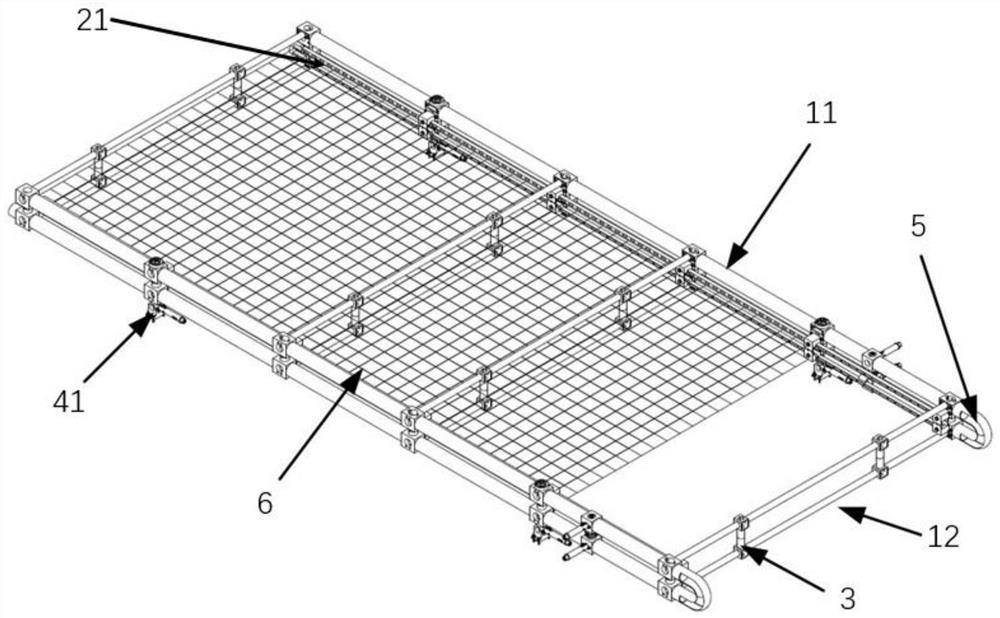
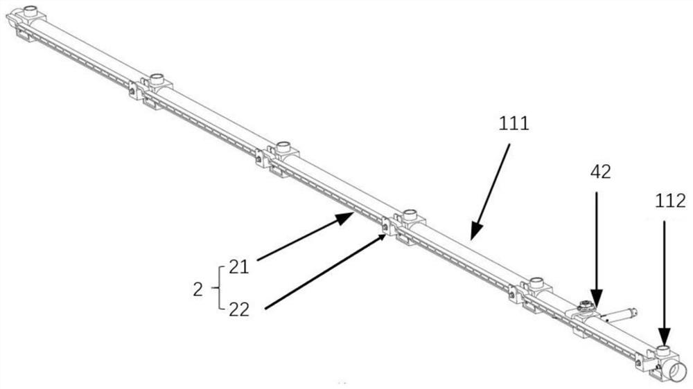
[0032] The present invention provides an expandable double-layer hybrid space planar antenna, which includes a planar film antenna frame 1 , a three-dimensional metal mesh antenna frame assembly 2 , a compression seat 3 , a compression release device 4 and a flexible hinge 5 . The planar film antenna frame 1 is a frame with a rectangular structure, including a spreading rod 11 and a cross bar 12. The two spreading rods 11 are parallel to each other. The two spreading rods 11 are connected and fixed by a plurality of cross bars 12. The number of the cross bars 12 is Two or more cross bars 12 located between two deployment bars 11 are parallel to each other. Preferably, the deployment rod 11 is formed by fastening and connecting a plurality of carbon fiber thin-walled rods 111 through compression joints 112. Further, the carbon fiber thin-walled rods 111 are formed by glueing thin-walled carbon fiber tubes. The thin-walled carbon fiber tube forms the carbon fiber thin-walled rod...

Embodiment 2

[0041] This embodiment 2 is formed on the basis of embodiment 1. Through the structural optimization design of the three-dimensional metal mesh antenna frame assembly, the metal mesh support rods on one side can be sequentially pressed on the inside of the frame, and a compression release device can be used. Realizing the folding and folding of multiple groups of metal mesh support rods on one side, the system structure is simplified, and the reduction in the number of pressing and releasing devices further reduces the overall weight of the system, which improves the reliability of the metal mesh support rods on-rail unlocking and releasing.

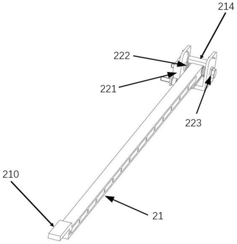
[0042] The metal mesh support rod 21 is designed as a structure with a Z-shaped end 210 , and the Z-shaped end 210 is located at the other end opposite to the end connected to the base 221 . Multiple sets of metal mesh support rods 21 connected to the same expansion rod 11 are connected end to end, and the way of connection is that the Z-...


PUM

PropertyMeasurementUnit
Folding angleaaaaaaaaaa

Abstract

The invention relates to an expandable double-layer hybrid space planar antenna in the technical field of spacecrafts, and the antenna comprises: a planar film antenna frame, which comprises expansion rods and cross rods, and the expansion rods and the cross rods are connected to form a rectangular structure; multiple groups of three-dimensional metal net antenna frame assemblies, which comprises metal net supporting rods and rotating seats, and are installed on the planar film antenna frame; a pressing and releasing device, which comprises a first pressing and releasing apparatus and a second pressing and releasing apparatus; two planar film antenna frames are connected through flexible hinges and folded to form a double-layer frame, a pressing base is connected with an upper cross rod and a lower cross rod in the double-layer frame, the first pressing and releasing apparatus is connected with an upper expansion rod and a lower expansion rod in the double-layer frame, and the metal net supporting rods are locked on the side faces of the expansion rods through the second pressing and releasing apparatus and are kept parallel. Folding of the planar film antenna and a metal net cavity is realized, and a higher storage ratio is realized through resultant force layout of an unfolding mechanism.

Description

technical field [0001] The invention relates to the technical field of spacecraft, in particular to a deployable double-layer hybrid space planar antenna. Background technique [0002] With the increasing demand for space-based VHF data exchange systems, deployable antennas are increasingly used on spacecraft. In order to achieve a higher data exchange capability, it is necessary to design a new thin-film deployable antenna. At the same time, the metal mesh is supported by the deploying mechanism to form a reflective cavity to realize the antenna function. Compared with other traditional planar antennas, film antennas and metal mesh reflectors can form higher-efficiency antennas, and can also achieve large size requirements in terms of size and volume. Due to the limitation of the envelope of the launch vehicle during the launch phase of the spacecraft, the antenna needs to be folded and pressed tightly on the star, and the spacecraft will be unfolded in place after enterin...

Claims


Application Information

Patent Timeline
IPC IPC(8): H01Q1/08
CPCH01Q1/08
Inventor 李奇王智磊李昊赵枝凯顾亦磊赵发刚孔祥森
Owner SHANGHAI SATELLITE ENG INST
Learn More