Robot eyeball structure

A robot and eyeball technology, applied in the parts and electrical components of TVs and color TVs, etc., can solve the problems of blind spots of collection and limited application scenarios, and achieve the effect of simple structure and improved accuracy.

Pending Publication Date: 2021-04-30
国科锐视(杭州)智能科技有限公司
View PDF0 Cites 0 Cited by
  • Summary
  • Abstract
  • Description
  • Claims
  • Application Information

AI Technical Summary

Problems solved by technology

[0002] After the traditional camera / mechanism is finished, its acquisition angle of view will be fixed, so there will be acquisition blind spots in the acquisition process, making the application scenarios more limited

Method used


Image

  • Robot eyeball structure
  • Robot eyeball structure
  • Robot eyeball structure

Examples


Embodiment 1

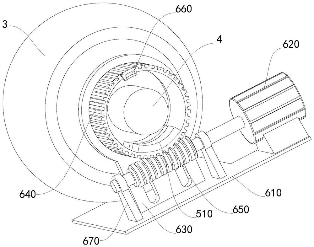
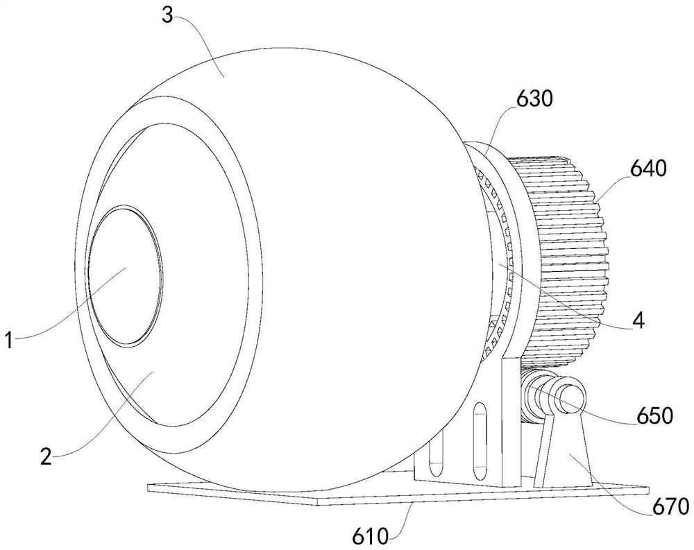
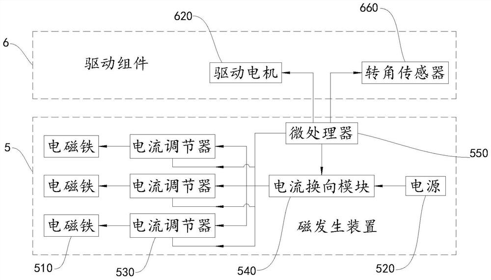
[0032] Such as Figure 1 ~ Figure 3 As shown, a robot eyeball structure includes an acquisition module 1, an eyeball 2, a ball socket 3, a magnetic column 4, a magnetic generating device 5, and a drive assembly 6. The eyeball 2 is movable in the ball socket 3, and the eyeball 2 and the ball socket 3 The cooperation is similar to that of a spherical hinge, the collection module 1 is arranged in the eyeball 2, and the collection module 1 is for video collection, image collection, etc., the type of the collection module 1 is not limited in the present invention, and it is enough to meet the use requirements according to actual needs; the magnetic column 4 is set at the tail end of the eyeball 2, and the axis line of the magnetic column 4 is in line with the axis line of the eyeball 2; the magnetic generating device 5 is set on the drive assembly 6, and driven by the drive assembly 6 to rotate around the magnetic column 4 .

Embodiment 2

[0034] Such as Figure 1 ~ Figure 3 As shown, the present embodiment is a further improvement on the basis of embodiment 1, specifically as follows:

[0035] Drive assembly 6 comprises base 610 and driving motor 620, and driving motor 620 is arranged on the base 610, and magnetic generator 5 is arranged on the output shaft of driving motor 620 eccentrically, and after driving motor 620 starts, will drive magnetic generator 5 to surround magnetic field. Column 4 rotates.

Embodiment 3

[0037] Such as Figure 1 ~ Figure 3 As shown, the present embodiment is a further improvement on the basis of embodiment 2, specifically as follows:

[0038] The driving assembly 6 also includes a fixed seat 630, a worm wheel 640 and a worm screw 650. The fixed seat 630 is arranged on the base 610. The worm wheel 640 is covered with the magnetic post 4. One end of the worm wheel 640 is rotationally connected with the fixed seat 630. Usually, the worm wheel 640 is connected to the fixed seat 630. Bearings are installed between the fixed seats 630 to ensure the accuracy and stability of the rotation through the bearings. The worm 650 is meshed with the worm wheel 640, and one end of the worm 650 is connected to the output shaft of the drive motor 620; the magnetic generator 5 is arranged on the worm wheel 640. In the inner circle, the distance between the magnetic column 4 and the magnetic generating device 5 is such that no matter which direction the magnetic column 4 deflects,...


PUM


Abstract

The invention relates to a robot eyeball structure which comprises a collection module, an eyeball, a ball socket, a magnetic column, a magnetic generation device and a driving assembly, wherein the eyeball is movably arranged in the ball socket, and the collection module is arranged in the eyeball; the magnetic column is arranged at the tail end of the eyeball, and the axis of the magnetic column is collinear with that of the eyeball; and the magnetic generation device is arranged on the driving assembly and is driven by the driving assembly to rotate around the magnetic column. The robot eyeball structure has the beneficial effects that when the collection module needs to adjust a collection direction, the driving assembly drives the magnetic generation device to rotate around the magnetic column to a preset position, and then the magnetic generation device is started to generate a magnetic force with a specific magnitude, direction and polarity, so as to drive the magnetic column to deflect a preset angle in a preset direction by taking the eyeball as a rotation center point, and indirectly adjusts the eyeball to deflect by the preset angle in the preset direction, thereby realizing adjustment of the collection direction, being wide in adjustable range, and having few collection blind zones.

Description

technical field [0001] The invention relates to the monitoring field, in particular to a robot eyeball structure. Background technique [0002] After the traditional camera / mechanism is finished, its acquisition angle of view will be fixed, so there will be acquisition blind spots in the acquisition process, making the application scenarios more limited. Contents of the invention [0003] The technical problem to be solved by the present invention is to provide a robot eyeball structure to overcome the above-mentioned deficiencies in the prior art. [0004] The technical solution of the present invention to solve the above-mentioned technical problems is as follows: a robot eyeball structure, including acquisition module, eyeball, ball socket, magnetic column, magnetic generating device and drive assembly, the eyeball movement is arranged in the ball socket, and the acquisition module is arranged in the eyeball The magnetic column is arranged at the tail end of the eyebal...

Claims


Application Information

Patent Timeline
Patent Type & Authority Applications(China)
IPC IPC(8): H04N5/225H04N5/232
CPCH04N23/50H04N23/63H04N23/695
Inventor 张永洲其他发明人请求不公开姓名
Owner 国科锐视(杭州)智能科技有限公司
Why Eureka
Try Eureka