Ground cleaning device for cleaning robot

A technology for cleaning robots and cleaning devices, applied in the field of robots, can solve the problems of inability to reflect the automation effect of robots, poor practicability, and complex transmission structure of buffer protection devices.

Active Publication Date: 2021-05-04
永康市宏奥工贸有限公司
View PDF9 Cites 3 Cited by
  • Summary
  • Abstract
  • Description
  • Claims
  • Application Information

AI Technical Summary

Problems solved by technology

The cleaning device of the existing sweeping robot cannot adjust the position of the cleaning head during use, and the cleaning practicability is not high
[0003] In order to solve the above problems, the Chinese patent (notification number: CN 110772180 A, announcement date: 2020.02.11) discloses a cleaning device for a sweeping robot. The device is equipped with a height adjustment device, which can adjust the

Method used


Image

  • Ground cleaning device for cleaning robot
  • Ground cleaning device for cleaning robot
  • Ground cleaning device for cleaning robot

Examples


Embodiment 1

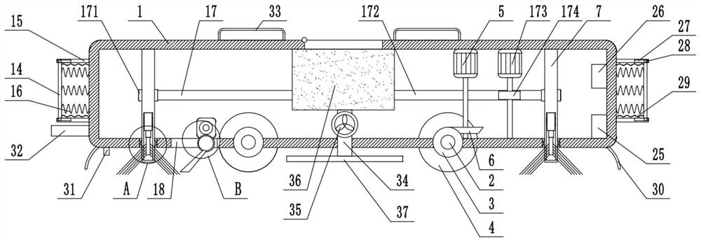
[0025] see Figure 1-5 , a floor cleaning device for a cleaning robot, comprising a circular housing 1, two sets of left and right horizontal rotating shafts 2 are mounted on the bottom wall of the housing 1, rollers 4 are fixedly installed on the rotating shaft 2, and the right rotating shaft A driven helical gear 3 is fixedly installed on the circumferential surface of the housing 1, a first motor 5 is fixedly installed on the inner top of the housing 1, and a driving helical gear 6 meshing with the driven helical gear 3 is fixedly installed on the output shaft of the first motor 5. A suction pipe 34 is fixedly installed in the middle of the bottom wall of the housing 1. The suction pipe 34 communicates with a suction pan 37 located below the bottom wall of the housing 1. The top of the suction pipe 34 communicates with a collection box fixed on the top of the housing 1. 36. A negative pressure fan 35 is fixedly installed on the dust suction pipe 34, a CPU processor 25 is fi...

Embodiment 2

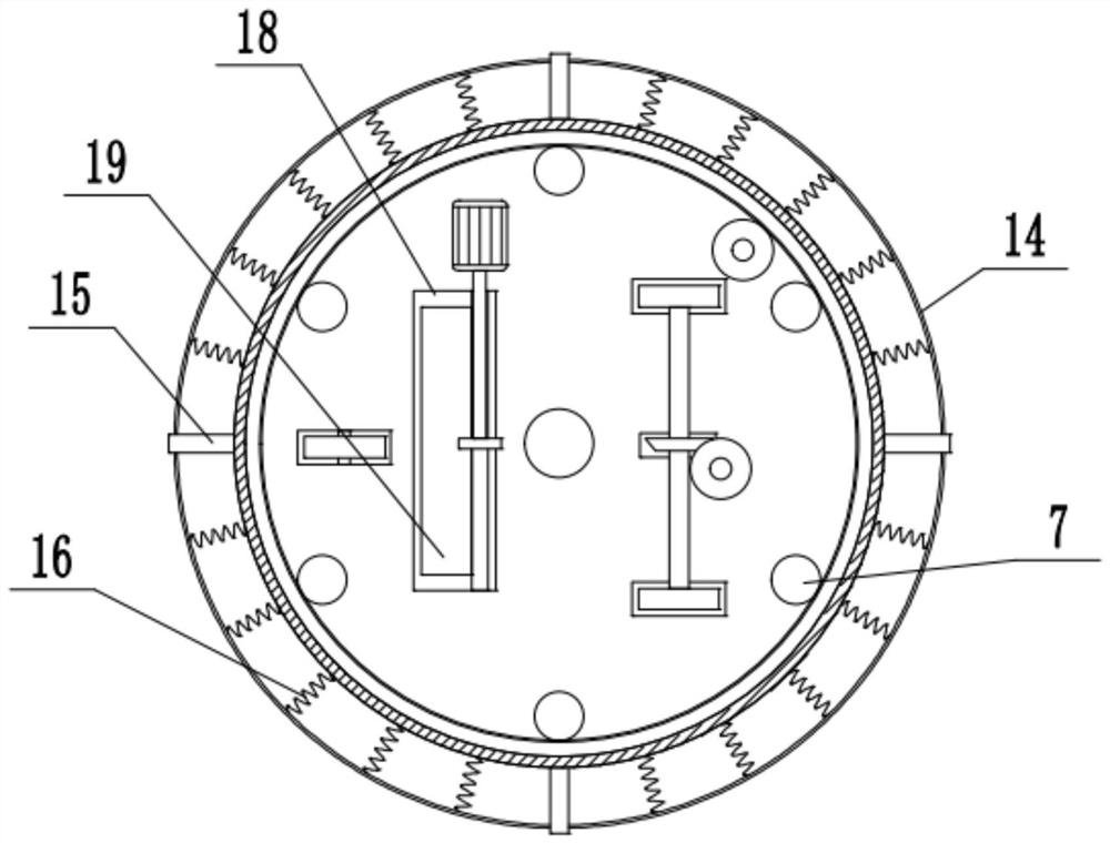
[0027]On the basis of Embodiment 1, the opposite side walls of the horizontal plates 15 on the upper and lower sides are respectively provided with chute 27, and a slide block 28 fixedly connected with the anti-collision ring 14 is slidably installed in the chute 27, and through the slide block 28 Cooperating with the chute 27 can effectively improve the stability of the anti-collision ring 14. On the circumferential side wall of the anti-collision ring 14, two sets of elastic sleeves 29 fixedly connected with the side wall of the housing 1 are fixedly installed. The buffer spring 16 is used for separation protection, the transmission part 17 includes an external gear 171 fixedly installed on the peripheral side wall of the rotating rod 7, a second motor 173 is fixedly installed on the inner top wall of the housing 1, and the output shaft of the second motor 173 is fixedly installed There is a transmission tooth plate 174, and the transmission tooth plate 174 is meshed with the...


PUM


Abstract

The invention belongs to the field of robots, and discloses a ground cleaning device for a cleaning robot. The ground cleaning device is technically characterized in that the ground cleaning device comprises a circular shell, a plurality of groups of vertical rotating rods which are annularly distributed are rotationally connected between the inner top wall and the inner bottom wall of the shell, the bottom ends of the rotating rods extend out of the bottom wall of the shell, and cylindrical cavities are formed in the rotating rods; multiple groups of vertical rectangular grooves which are uniformly distributed at equal intervals and located below the shell are formed in the side wall of the rotating rod on the outer side of the cavity, rotating shafts are rotatably mounted in the rectangular grooves, electric telescopic rods are fixedly mounted at the top in the cavity downwards, and lifting columns are fixedly mounted on output shafts of the electric telescopic rods; multiple sets of plastic brushes which are distributed at equal intervals, incline downwards, are fixedly connected with the rotating shaft and extend out of the rectangular groove are fixedly installed on the circumferential side wall of the lifting column, the multiple sets of rotating rods are jointly connected with a transmission part, a horizontal groove is formed in the bottom wall of the shell, and first rotating rods are rotationally connected to the front inner wall and the rear inner wall of the horizontal groove; and a shovel plate is fixedly mounted on the circumferential side wall of the first rotating rod.

Description

technical field [0001] The invention relates to the field of robots, in particular to a floor cleaning device for a cleaning robot. Background technique [0002] Sweeping robot, also known as smart vacuum cleaner, is a kind of smart household appliances. It can automatically complete the floor cleaning work in the room by virtue of certain artificial intelligence. Generally, the ground debris is first absorbed into its own garbage storage by brushing and vacuuming. box, thus completing the function of floor cleaning. The cleaning device of the existing sweeping robot cannot adjust the position of the cleaning head during use, and the cleaning practicability is not high. [0003] In order to solve the above problems, the Chinese patent (notification number: CN 110772180 A, announcement date: 2020.02.11) discloses a cleaning device for a sweeping robot. The device is equipped with a height adjustment device, which can adjust the position of the cleaning head in the vertical d...

Claims


Application Information

Patent Timeline
IPC IPC(8): A47L11/24A47L11/40
CPCA47L11/24A47L11/4094A47L11/4038A47L11/4077A47L11/4036A47L2201/00
Inventor 左国才
Owner 永康市宏奥工贸有限公司
Why Eureka
Try Eureka