Automatic assembly welding clamp for axle housing flanges

A technology for welding fixtures and axle housing flanges, which is applied in welding equipment, auxiliary welding equipment, welding/cutting auxiliary equipment, etc., and can solve problems such as inability to adapt to the fixing of multiple parts, inability to flip axle housing components, and single fixture structure , to achieve the effect of avoiding manual repeated flipping of the workpiece

Active Publication Date: 2021-05-04
XIAMEN AEROSPACE SIERT ROBOT SYST CO LTD
View PDF9 Cites 3 Cited by
  • Summary
  • Abstract
  • Description
  • Claims
  • Application Information

AI Technical Summary

Problems solved by technology

[0003]The object of the present invention is to provide an automatic butt joint welding fixture for axle housing flanges, which solves the problem that the fixture structure in the prior art is single and cannot adapt to multiple parts on the same Fixing of equipment and inability to flip axle housing components

Method used


Image

  • Automatic assembly welding clamp for axle housing flanges
  • Automatic assembly welding clamp for axle housing flanges
  • Automatic assembly welding clamp for axle housing flanges

Examples


Embodiment 1

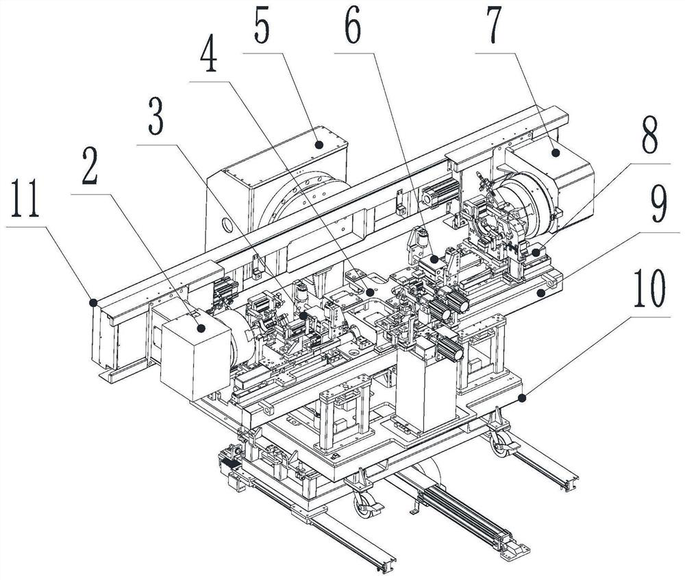
[0033] Such as figure 1 As shown, an axle housing flange automatic butt welding fixture includes a turning device 11, a clamping device 8, and a mounting plate 9 for installing the clamping device 8. The clamping device 8 includes a second clamping device for clamping the two ends of the axle housing respectively. A flange plate positioning device 3, a second flange plate positioning device 6, an axle housing smoothing device 4 is arranged between the first flange plate positioning device 3 and the second flange plate positioning device 6, and the axle housing is smoothed The device 4, the first flange positioning device 3 and the second flange positioning device 6 are all connected to the mounting plate 9; on the side of the mounting plate 9, there is also a lifting and positioning assembly for clamping with the axle housing smoothing device 4 10. The lifting and positioning assembly 10 is vertically arranged on the ground along the horizontal direction of the axle housing sm...

Embodiment 2

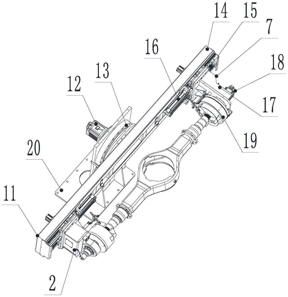
[0036] This embodiment is carried out on the basis of embodiment 1, as figure 2 As shown, the large overturn structure 5 includes a cabinet 20, a first motor 12 is arranged in the cabinet 20, a frame beam 14 is arranged on the side of the cabinet 20, the frame beam 14 is connected with the cabinet 20 through a slewing bearing 13, and the active end chuck device 7 Connected to one end of the frame beam 14, the driven end chuck device 2 is connected to the other end of the frame beam 14; the chassis 20 can be fixedly installed on the ground, driven by the first motor 12 in the chassis 20 and connected to the slewing bearing 13 The frame crossbeam 14 rotates, and then the clamping workpiece between the active end chuck device 7 and the driven end chuck device 2 will be tilted, and then the active end chuck device 7 and the driven end chuck device 2 are aligned on the same horizontal plane. The height difference is formed, and the follow-up manual welding or mechanical welding ob...

Embodiment 3

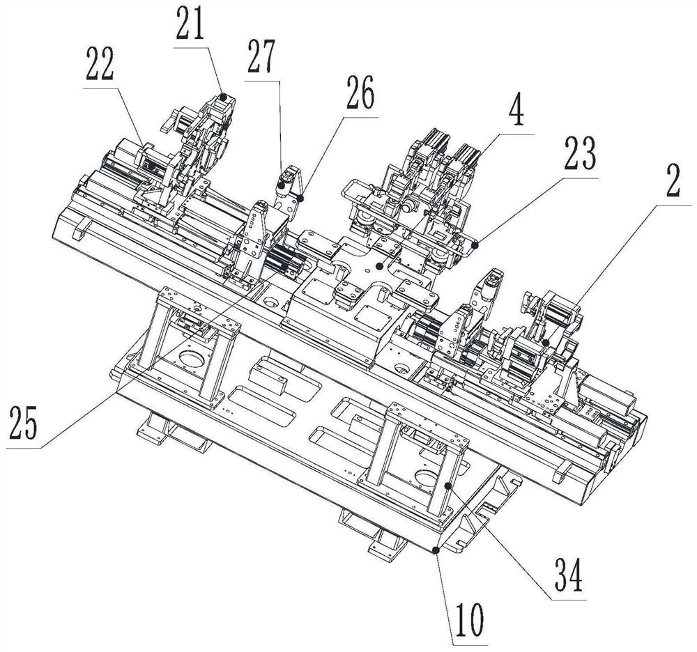
[0040] This embodiment is carried out on the basis of embodiment 2, such as Figure 3-5 As shown, first, the first flange positioning device 3 and the second flange positioning device 6 both include a clamping assembly 21, and the bottoms of the two clamping assemblies 21 are horizontally provided with a second slide rail along the long axis of the mounting plate 9 24. The two second slide rails 24 are connected to the mounting plate 9, and the sides of the two clamping components 21 are provided with a centering clamping device for pushing the first flange positioning device 3 and the second flange positioning device 6 respectively. The second air cylinder 25 is used, and the two second air cylinders 25 are all connected to the mounting plate 9; wherein the clamping assembly 21 can adopt a clamping device 8 with a symmetrical structure, in order to ensure that the clamping assembly 21 is adjusted to the corresponding position, the second slide rail 24 is designed below the tw...


PUM


Abstract

The invention discloses an automatic assembly welding clamp for axle housing flanges, belongs to the technical field of axle clamp equipment, and aims to solve the problems that in the prior art, a clamp is single in structure and cannot adapt to fixation of a plurality of parts on the same equipment, and an axle housing assembly cannot be overturned. The automatic assembly welding clamp for the axle housing flanges comprises an overturning device and a clamping device, wherein the overturning device comprises a large overturning structure, as well as a driving end chuck device and a driven end chuck device which are connected to the two ends of the large overturning structure respectively; the clamping device comprises a first flange plate positioning device and a second flange plate positioning device which clamp the two ends of an axle housing respectively; an axle housing smoothening device is arranged between the first flange plate positioning device and the second flange plate positioning device; and a lifting positioning assembly matched with the axle housing smoothening device for clamping is further arranged on the side face of a mounting plate, so that workpieces of different sizes are fixed, and the problem that the workpieces of different sizes are not matched is avoided.

Description

technical field [0001] The invention belongs to the technical field of axle fixture equipment, in particular to an automatic butt joint welding fixture for flanges of axle housings. Background technique [0002] The existing axle housing requires working fixtures and fixtures before welding, which will be tailor-welded from the center shell, left bridge tube, right bridge tube and flange parts. The existing fixtures are generally positioned and welded manually, which has high labor intensity and manufacturing problems. The problems of low precision and low production efficiency have arisen, and some mechanical fixtures are used to clamp the components of the axle housing. However, the fixing method of the mechanical fixture is single, and it can only be fixed one-to-one for the same size of welding parts, which cannot meet various sizes. The fixed requirement of the workpiece brings the problem of incompatibility. The position of the fixture needs to be adjusted repeatedly b...

Claims


Application Information

Patent Timeline
Patent Type & Authority Applications(China)
IPC IPC(8): B23K37/04B23K37/047
CPCB23K37/0443B23K37/047
Inventor 黄敏何俊
Owner XIAMEN AEROSPACE SIERT ROBOT SYST CO LTD
Why Eureka
Try Eureka