Terminal equipment

A terminal equipment and motion technology, applied in the direction of instruments, calculations, character and pattern recognition, etc., can solve the problems of acquisition blind spots and signals that cannot completely cover target objects, etc., to reduce acquisition blind spots, improve user experience, and shorten acquisition time Effect

Pending Publication Date: 2021-05-04
BEIJING XIAOMI MOBILE SOFTWARE CO LTD
View PDF0 Cites 0 Cited by
  • Summary
  • Abstract
  • Description
  • Claims
  • Application Information

AI Technical Summary

Problems solved by technology

During the face recognition process, since the emission field of view of the emission module is smaller than the acquisition field of view of the image acquisition module, the signal emitted by the emission module cannot completely cover the target object, which in turn causes the image acquisition module to fail when the acquisition is completed. There is a collection blind area when the light signal reflected by the target object

Method used


Image

  • Terminal equipment
  • Terminal equipment
  • Terminal equipment

Examples


Embodiment Construction

[0048] Reference will now be made in detail to the exemplary embodiments, examples of which are illustrated in the accompanying drawings. When the following description refers to the accompanying drawings, the same numerals in different drawings refer to the same or similar elements unless otherwise indicated. The implementations described in the following exemplary examples do not represent all implementations consistent with the present invention. Rather, they are merely examples of apparatuses and methods consistent with aspects of the invention as recited in the appended claims.

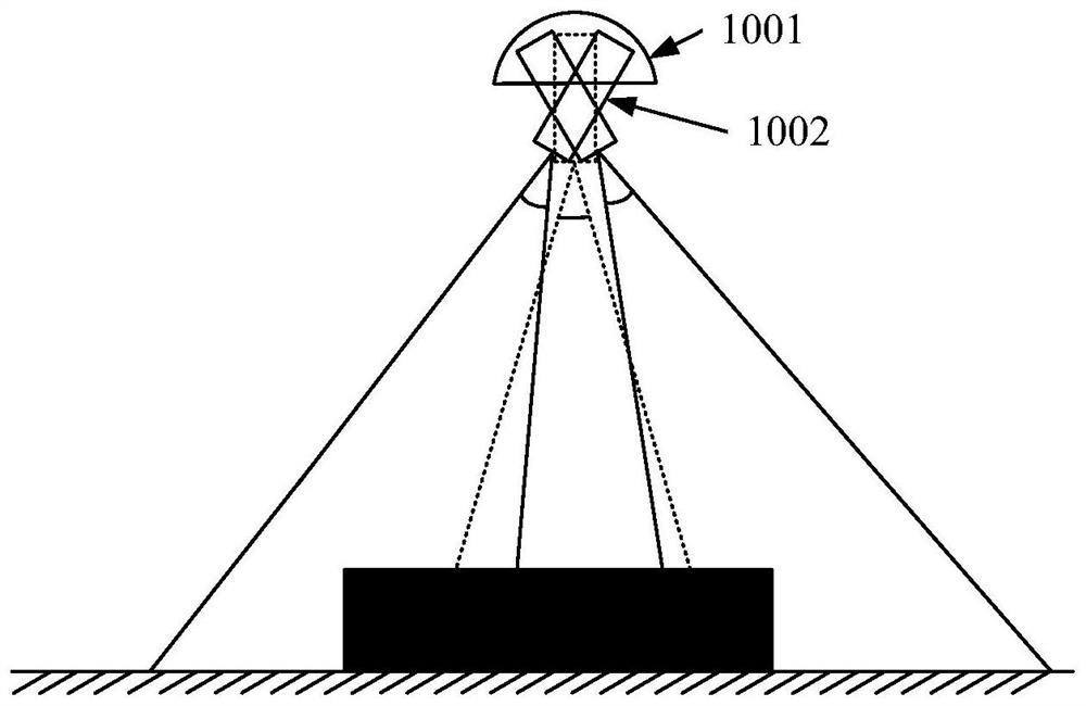
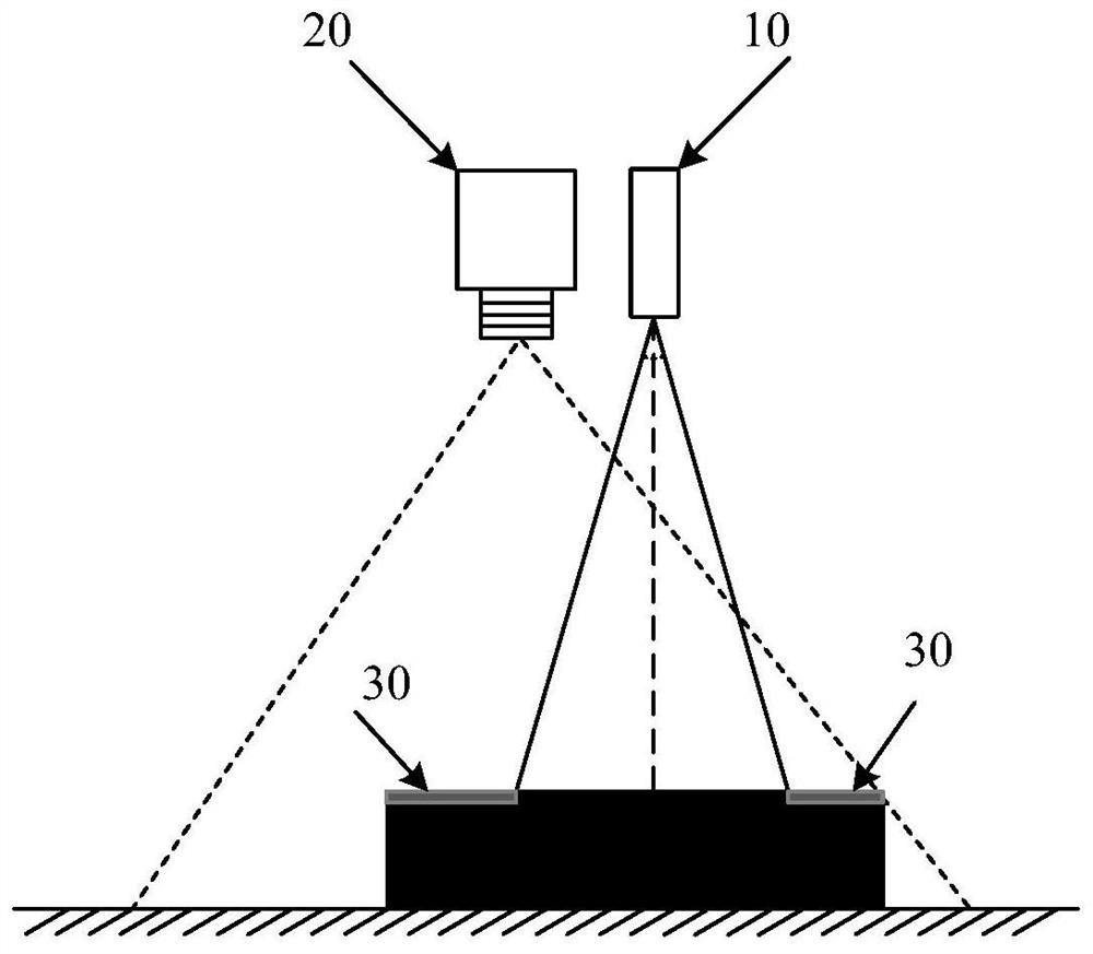
[0049] The embodiment of the present disclosure proposes a terminal device. figure 1 is a schematic illustration of a terminal device according to an exemplary embodiment Figure 1 . Such as figure 1 As shown, the terminal equipment includes at least:

[0050] a housing having a first opening;

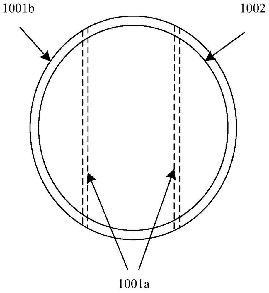
[0051] The launch module is located in the casing, wherein the launch module includes:

[0052]...


PUM


Abstract

The invention relates to terminal equipment. The terminal equipment comprises: a housing which is provided with a first opening; and a transmitting module located in the shell, and the transmitting module comprises a movable support, and a moving body which is mounted on the movable support and can move along the movable support. When the moving body is located at a first position, the moving body has an emission field angle of a first orientation; when the moving body is located at a second position, the moving body has an emission field angle of a second orientation; and the moving body transmits an optical signal to the outside of the shell through the first opening. According to the embodiment of the invention, the transmitting range of the optical signal can be increased by adjusting the position of the moving body on the movable bracket, so that the transmitting range can cover the target object, and the acquisition blind area is reduced.

Description

technical field [0001] The present disclosure relates to the technical field of electronic equipment, and in particular, to a terminal equipment. Background technique [0002] With the development of face recognition technology of terminal equipment, the transmitting module and image acquisition module on the terminal equipment are widely used in face recognition. Currently, both the launch module and the image acquisition module are fixedly installed on the terminal equipment. During the face recognition process, since the emission field of view of the emission module is smaller than the acquisition field of view of the image acquisition module, the signal emitted by the emission module cannot completely cover the target object, which in turn causes the image acquisition module to fail when the acquisition is completed. There is a collection blind area when the light signal reflected by the target object. Contents of the invention [0003] The present disclosure provide...

Claims


Application Information

Patent Timeline
Patent Type & Authority Applications(China)
IPC IPC(8): G06K9/00G06K9/20
CPCG06V40/166G06V10/147
Inventor 郝宁
Owner BEIJING XIAOMI MOBILE SOFTWARE CO LTD
Why Eureka
Try Eureka