A kind of auxiliary system for maintenance of high voltage switchgear

A high-voltage switchgear and auxiliary system technology, applied in the field of switchgear, can solve the problems of inconvenient maintenance operation and narrow internal space, and achieve the effect of improving the maintenance space, improving the maintenance space and improving the interval.

Active Publication Date: 2022-07-12
国网黑龙江省电力有限公司齐齐哈尔供电公司 +1
View PDF4 Cites 0 Cited by
  • Summary
  • Abstract
  • Description
  • Claims
  • Application Information

AI Technical Summary

Problems solved by technology

[0006] The purpose of the present invention is to solve the problems of narrow internal space and inconvenient maintenance operation in the prior art, and propose a high-voltage switchgear maintenance auxiliary system

Method used


Image

  • A kind of auxiliary system for maintenance of high voltage switchgear
  • A kind of auxiliary system for maintenance of high voltage switchgear
  • A kind of auxiliary system for maintenance of high voltage switchgear

Examples


Embodiment 1

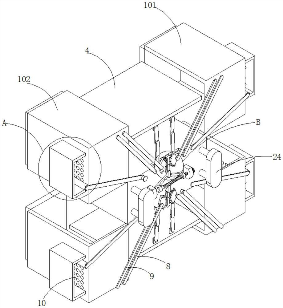
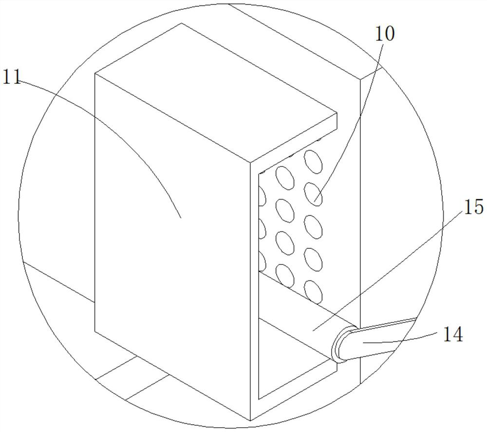
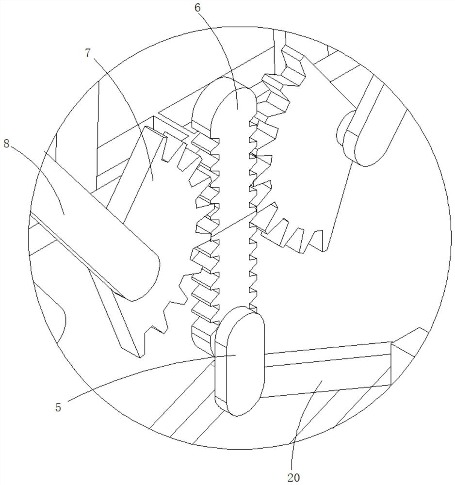
[0041] refer to Figure 1-10 , a high-voltage switchgear maintenance auxiliary system, including an upper cabinet 1, a middle cabinet 2 and a lower cabinet 3, and the upper cabinet 1, the middle cabinet 2 and the lower cabinet 3 are arranged in sequence along the vertical direction, and the upper cabinet 1 and the lower cabinet 3 The electrical equipment mounting plate 4 is slidably connected to each other. The back of the middle cabinet 2 is provided with installation components. The upper cabinet 1 and the lower cabinet 3 both include a first cabinet 101 and a second cabinet 102 that are connected to each other. The first cabinet 101 and the The second cabinet 102 is symmetrically arranged about the central axis of the middle cabinet 2, and both the first cabinet 101 and the second cabinet 102 are slidably connected to the middle cabinet 2, and the back of the middle cabinet 2 is also connected with a telescopic assembly. The end is fixed with a vertically arranged transmiss...

Embodiment 2

[0049] refer to Figure 1-11 , a high-voltage switchgear maintenance auxiliary system, including an upper cabinet 1, a middle cabinet 2 and a lower cabinet 3, and the upper cabinet 1, the middle cabinet 2 and the lower cabinet 3 are arranged in sequence along the vertical direction, and the upper cabinet 1 and the lower cabinet 3 The electrical equipment mounting plate 4 is slidably connected to each other. The back of the middle cabinet 2 is provided with installation components. The upper cabinet 1 and the lower cabinet 3 both include a first cabinet 101 and a second cabinet 102 that are connected to each other. The first cabinet 101 and the The second cabinet 102 is symmetrically arranged about the central axis of the middle cabinet 2, and both the first cabinet 101 and the second cabinet 102 are slidably connected to the middle cabinet 2, and the back of the middle cabinet 2 is also connected with a telescopic assembly. The end is fixed with a vertically arranged transmiss...


PUM


Abstract

The invention discloses an auxiliary system for overhauling a high-voltage switch cabinet and a method for using the same, belonging to the technical field of switch cabinets. An auxiliary system for maintenance of high-voltage switch cabinets, comprising an upper cabinet, a middle cabinet and a lower cabinet, wherein the upper cabinet, the middle cabinet and the lower cabinet are arranged in sequence along the vertical direction, and the upper cabinet and the lower cabinet are both slidably connected with electrical equipment installation boards, The back of the middle cabinet is provided with installation components, the upper cabinet and the lower cabinet both include a first cabinet body and a second cabinet body that are butted to each other, the first cabinet body and the second cabinet body are symmetrically arranged about the central axis of the middle cabinet, and the first cabinet body and the second cabinet body The cabinet body and the second cabinet body are both slidably connected with the middle cabinet, the back of the middle cabinet is also connected with a telescopic assembly, the telescopic end of the telescopic assembly is fixed with a vertically arranged transmission tooth plate through the connecting rod, and the transmission tooth plate slides with the middle cabinet. The invention realizes the automatic opening function of the shell of the switch cabinet, can greatly increase the maintenance space during the maintenance of the switch cabinet, and improve the efficiency and accuracy of the maintenance.

Description

technical field [0001] The invention relates to the technical field of switch cabinets, in particular to an auxiliary system for maintenance of high-voltage switch cabinets. Background technique [0002] The switch cabinet is a kind of electrical equipment. The outside line of the switch cabinet first enters the main control switch in the cabinet, and then enters the sub-control switch. Each branch is set according to its needs. Such as instrumentation, automatic control, motor magnetic switch, various AC contactors, etc., and some also have high-voltage room and low-voltage room switch cabinets, high-voltage busbars, such as power plants, etc. load shedding. The main function of the switchgear is to open and close, control and protect the electrical equipment in the process of power generation, transmission, distribution and power conversion in the power system. The components in the switch cabinet are mainly composed of circuit breakers, isolating switches, load switches...

Claims


Application Information

Patent Timeline
Patent Type & Authority Patents(China)
IPC IPC(8): H02B1/30H02B1/32H02B1/28B08B1/04H02B1/56
CPCH02B1/308H02B1/32H02B1/28B08B1/04B08B1/002H02B1/565H02B3/00
Inventor 不公告发明人
Owner 国网黑龙江省电力有限公司齐齐哈尔供电公司
Why Eureka
Try Eureka