The gate mechanism of the steel ball conveying insulation pipe

A technology of heat preservation pipes and steel balls, which is applied in the direction of mechanical equipment, engine components, valve operation/release devices, etc., to achieve the effect of performance improvement

Inactive Publication Date: 2017-11-07
米易华星钒钛科技有限责任公司
View PDF5 Cites 0 Cited by
  • Summary
  • Abstract
  • Description
  • Claims
  • Application Information

AI Technical Summary

Problems solved by technology

[0008] However, just letting the high-temperature steel balls fall freely from the insulation pipe with gravity does not perfectly guarantee that each steel ball has enough self-tempering time, so the equipment needs to be further improved

Method used


Image

  • The gate mechanism of the steel ball conveying insulation pipe
  • The gate mechanism of the steel ball conveying insulation pipe

Examples


Embodiment Construction

[0020] Below in conjunction with accompanying drawing and embodiment the present invention is further described:

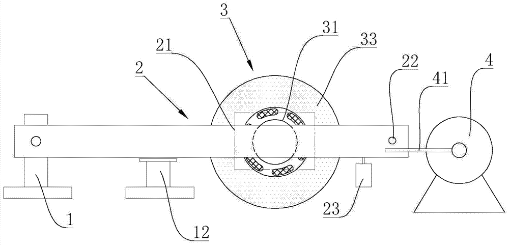
[0021] The gate mechanism of the steel ball conveying insulation pipe is characterized in that it includes a base 1 and a cross bar 2, the base 1 is fixed, one end of the cross bar 2 is hinged to the base 1, and the cross bar 2 is provided with a stopper 21, also includes a driving mechanism for driving the cross bar 2 to swing around its hinge point.

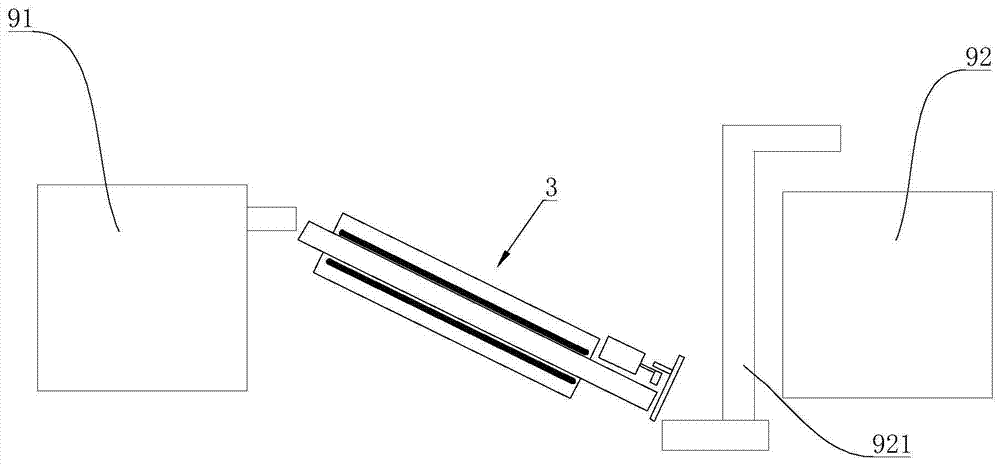
[0022] The gate mechanism of the present invention is used for intermittently opening the steel ball conveying insulation pipe 3 of the ball mill steel ball manufacturing equipment. Such as figure 1 As shown, the steel ball conveying heat preservation pipe 3 is located between the forging machine 91 and the quenching pool 92, the steel ball conveying heat preservation pipe 3 is arranged obliquely, and the high temperature steel balls sent out by the forging machine 91 can roll along the steel ball conveying heat p...


PUM


Abstract

The invention relates to a gate mechanism of a steel ball conveying insulating pipe. The gate mechanism comprises a base and a cross rod. The base is fixedly arranged. One end of the cross rod is hinged to the base. The cross rod is provided with a stop piece part. The gate mechanism further comprises a drive mechanism used for driving the cross rod to swing around a hinged point of the cross rod. By means of the gate mechanism of the steel ball conveying insulating pipe, the stop piece part on the cross rod can block the passing path of the steel ball conveying insulating pipe, the drive mechanism is utilized for driving the cross rod to swing around the hinged point intermittently, and when the cross rod swings to the greatest degree, the stop piece part is separated from the original block position, the path of the insulating pipe is open, accordingly, the gate opening function is achieved, and steel balls can pass through the insulating pipe. At other time, the steel balls are blocked by the stop piece part and left in the insulating pipe, the steel balls have enough self-tempering time, and after later quenching treatment, the performance of the steel balls is obviously improved.

Description

technical field [0001] The invention relates to a ball mill steel ball manufacturing equipment, in particular to a gate mechanism for the steel ball conveying insulation pipe. Background technique [0002] The ball mill is a commonly used material crushing equipment. Its basic structure is that a large number of steel balls are stored in a cylinder. When the ball mill is working, the material is put into the cylinder, and the cylinder is driven to rotate. The steel balls and materials inside the cylinder continue to roll and sprinkle, and the steel balls continuously form a knocking effect on the material to crush the material. In addition, when the material tumbles in the cylinder, it also has the effect of surface grinding. [0003] Based on the working principle of the ball mill, the steel ball has to bear the impact of collision and wear and tear continuously, which requires the steel ball to have sufficient strength and toughness, otherwise the steel ball will be broke...

Claims


Application Information

Patent Timeline
Patent Type & Authority Patents(China)
IPC IPC(8): F16K31/44F16K31/04
CPCF16K31/043F16K31/44
Inventor 黄军黄发奎杨文
Owner 米易华星钒钛科技有限责任公司
Why Eureka
Try Eureka