Eureka AIR delivers breakthrough ideas for toughest innovation challenges, trusted by R&D personnel around the world.

Hydrops therapeutic apparatus used for thoracic surgery department

A technology of therapeutic apparatus and thoracic surgery, applied in the direction of suction equipment, etc., can solve the problems of broken bellows, inability to perform normal drainage, and cross kink of pushing grids.

Inactive Publication Date: 2021-05-07
刘英兰
View PDF0 Cites 0 Cited by
  • Summary
  • Abstract
  • Description
  • Claims
  • Application Information

AI Technical Summary

Problems solved by technology

When the existing thoracic surgical effusion treatment device draws and drains drainage, due to the great flexibility of the bellows, the fluid in the needle only flows into the liquid collection bottle through the bellows under the action of gravity. Rotation will cause cross kinks between the push grates, so that the inside of the bellows will have broken flow and uneven tension, which will cause incomplete or normal drainage of the bellows

Method used


Image

  • Hydrops therapeutic apparatus used for thoracic surgery department
  • Hydrops therapeutic apparatus used for thoracic surgery department
  • Hydrops therapeutic apparatus used for thoracic surgery department

Examples


Embodiment 1

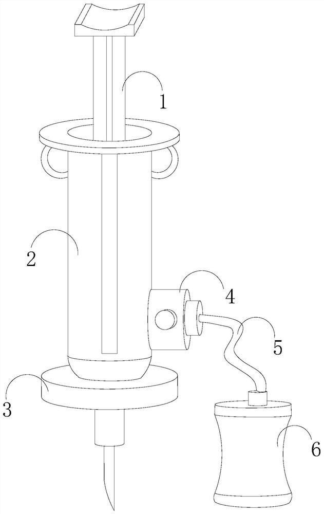
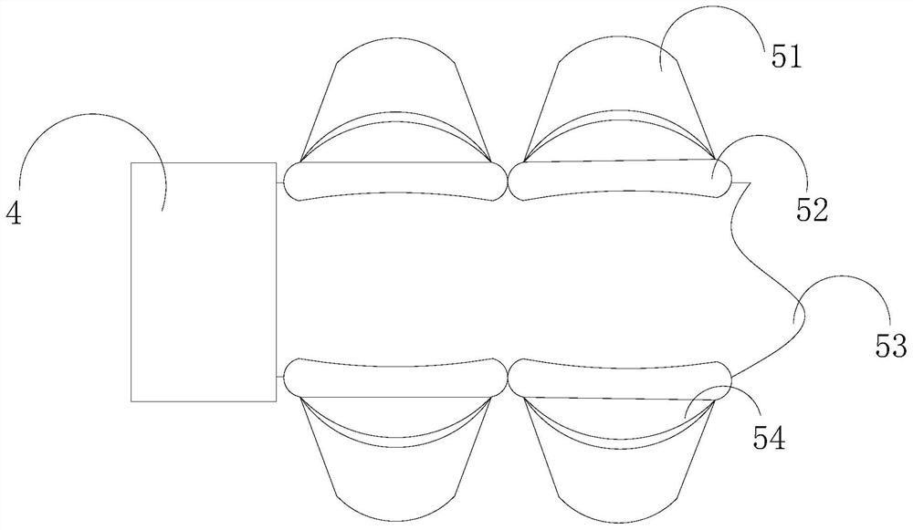
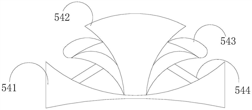
[0028] Such as Figure 1-Figure 3 As shown, the present invention provides a thoracic surgery effusion treatment instrument, its structure includes a push handle 1, a needle tube 2, an extraction needle 3, a communication cavity 4, a bellows 5, and a liquid collection bottle 6, and the push handle 1 is inserted into the needle tube 2, the bottom of the needle tube 2 is fixedly connected with the extraction needle 3, and one side of the needle tube 2 is welded and connected with a communication cavity 4, the communication cavity 4 communicates with the liquid collection bottle 6 through the bellows 5, and the bellows 5 includes A grating 51, a buckle 52, a hose 53, and a booster device 54. A booster device 54 is installed between the grating 51 and the buckle 52. The buckle 52 is welded on both sides of the hose 53. The soft The tube 53 is fixedly connected to one side of the communication chamber 4, and the booster device 54 includes a base 541, a supporting structure 542, an ...

Embodiment 2

[0030] Such as Figure 4-Figure 7 As shown, on the basis of Embodiment 1, the present invention combines the mutual cooperation of the following structural components. The supporting structure 542 includes an extension piece 421, a clip rail 422, a rotating shaft 423, a connecting column 424, and an elastic member 425. The rotating shaft 423 is fixedly connected inside the arc of the grating 51, and the rotating shaft 423 is hingedly connected to the clamping rail 422 through the connecting column 424. The elastic member 425 is connected, and the adjustment device 543 includes a subduction groove 431, a top column 432, a connecting blade 433, an air cushion 434, a running-in strip 435, and a pressure dividing structure 436. The bottom of the subduction groove 431 is welded and connected to the support rod 544, In addition, both sides of the subduction groove 431 are hingedly connected with clamping leaves 433, the air cushion 434 is fixedly connected to the bottom of the clamp...


PUM


Abstract

The invention discloses a hydrops therapeutic apparatus used for the thoracic surgery department. The hydrops therapeutic apparatus used for the thoracic surgery department structurally comprises a pushing handle, needle tubing, an extraction needle, a communication cavity, a corrugated pipe and a liquid collection bottle, wherein the pushing handle is inserted into the needle tubing; the bottom of the needle tubing is fixedly connected with the extraction needle; one side of the needle tubing is welded and connected with the communication cavity; and the communication cavity communicates with the inside of the liquid collection bottle through the corrugated pipe. A power assisting device of the hydrops therapeutic apparatus is internally provided with a supporting structure and a regulation device, the supporting structure and the regulation device are cooperated on the inner side of a supporting rod, when the inside of the corrugated pipe generates radial rotation due to gravity, force is firstly applied to the top of the supporting structure, so that the supporting structure generates preliminary torsion movement on the regulation device, and under the fixed restriction of the regulation device, the supporting structure is clamped on the bottom of a stripe grid in a limit crossed form so as to avoid a phenomenon that the stripe grid is downwards extruded to generate crossed twisting.

Description

technical field [0001] The invention relates to the field of medical equipment for thoracic surgery, in particular to a treatment instrument for effusion in thoracic surgery. Background technique [0002] Excessive fluid in the pleural cavity for any reason is called pleural effusion, commonly known as pleural effusion. We often say pleural effusion, but it is actually pleural effusion. There is fluid in the pleural cavity of normal people, which plays a lubricating role during respiratory movement, but the amount of fluid in the pleural cavity is not constant. Even normal people have fluid formation and absorption every day. The fluid in the pleural cavity is reabsorbed from the venous end of the capillaries, and the rest of the fluid is recycled to the blood by the lymphatic system. Filtration and absorption are in a dynamic balance. When the existing thoracic surgical effusion treatment device draws and drains drainage, due to the great flexibility of the bellows, the ...

Claims


Application Information

Patent Timeline
IPC IPC(8): A61M1/00
Inventor 刘英兰
Owner 刘英兰
Why Eureka
Eureka Blog
Learn More