
Steel clamping device, steel clamping structure and method for improving straightness of steel rail ends before straightening

A technology of straightness and rail, which is applied in the field of metallurgy, and can solve problems such as the bending of the rail head at the end of the rail

Pending Publication Date: 2021-05-07
PANGANG GRP PANZHIHUA STEEL & VANADIUM
View PDF0 Cites 0 Cited by
  • Summary
  • Abstract
  • Description
  • Claims
  • Application Information

AI Technical Summary

Problems solved by technology

[0005] The present invention firstly provides a steel clamping device, which is used to install on the side of the static beam of the cooling bed, so as to solve the problem of the rail head bending at the end of the rail after the reverse pre-bending of the rail and before straightening, and the purpose is to improve the safety of the rail before straightening. straightness

Method used


Image

  • Steel clamping device, steel clamping structure and method for improving straightness of steel rail ends before straightening
  • Steel clamping device, steel clamping structure and method for improving straightness of steel rail ends before straightening

Examples


Embodiment Construction

[0021] The present invention will be further described below in conjunction with accompanying drawing.

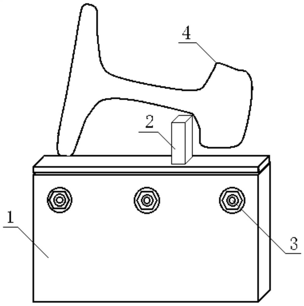
[0022] refer to figure 1 , the first subject of the present invention is a clamping steel device for improving the straightness of the rail end before leveling, including a box 1 and a clip 2, one or more installation grooves are arranged on the top of the box 1, and at least one clip 2 is columnar , The lower part of the clip 2 is assembled in the installation groove, and the upper part of the clip 2 is located outside the installation groove. The box 1 plays the role of accommodating and supporting the lower end of the fixing clip 2, and the mounting groove is preferably vertical.

[0023] When an installation groove is arranged on the top of the box 1, there is one clip 2. When the top of box 1 is provided with a plurality of mounting grooves, the size of each mounting groove is preferably consistent, and each mounting groove is arranged at equal intervals and the cent...


PUM

PropertyMeasurementUnit
Lengthaaaaaaaaaa
Heightaaaaaaaaaa
Depthaaaaaaaaaa

Abstract

The invention discloses a steel clamping device, steel clamping structure and method for improving the straightness of steel rail ends before straightening, and relates to the field of metallurgy. The problem that railhead bending happens to steel rail ends after steel rails are reversely pre-bent and before the steel rails are straightened is solved. The steel clamping device for improving the straightness of the steel rail ends before straightening comprises a box and a clamp, a mounting groove is formed in the top of the box, the lower portion of the clamp is assembled in the mounting groove, and the upper portion of the clamp is located outside the mounting groove. The steel clamping structure for improving the straightness of the steel rail ends before straightening comprises a cooling bed, a steel rail and the steel clamping device, the box is fixedly installed on the side face of a static beam, the steel rail is reversely pre-bent and arranged on the cooling bed, and the top of the clamp is clamped at the railhead-rail web connecting position or the rail web-rail bottom connecting position of the steel rail. According to the method for improving the straightness of the steel rail ends before straightening comprises the following steps, after the steel rail is subjected to finish rolling and put on the cooling bed, reverse pre-bending is carried out on the steel rail by a pre-bending trolley; the steel rail is clamped by the steel clamping structure; and a stepping beam is lifted, and the steel rail is lifted along with the stepping beam and is separated from the clamp. The steel clamping device, the steel clamping structure and the method are used for improving the straightness of the steel rail before straightening.

Description

technical field [0001] The invention relates to the technical field of metallurgy, in particular to a steel clamping device, a steel clamping structure and a method for improving the straightness of rail ends before straightening. Background technique [0002] After the rail is rolled, it enters the cooling bed for cooling, and the whole rail is relatively straight when it first enters the cooling bed. Without pre-bending, the rail will bend towards the rail head with more heat capacity after it has cooled completely. In order to reduce the curvature of the rail before straightening, the rail needs to be pre-bent in the opposite direction when it is just on the cooling bed after rolling. [0003] When the rail is reversely pre-bent, the rail is lifted flat under the action of the pre-bend, and the center line of the rail waist is basically horizontal; after the reverse pre-bend, when the rail is placed on the static beam of the cooling bed, the rail is naturally placed sta...

Claims


Application Information

Patent Timeline
IPC IPC(8): B21D7/00B21B15/00
CPCB21B15/00B21D7/00
Inventor 陶功明陈元福陈定龙李小红唐静谭军邓国军
Owner PANGANG GRP PANZHIHUA STEEL & VANADIUM
Learn More