Perforating device for binding financial materials

A punching device and data technology, applied in the field of financial data management, can solve the problems of uneven punching, time-consuming and labor-intensive, easy to be injured, etc.

Inactive Publication Date: 2021-05-07
重庆丹含科技有限公司
View PDF0 Cites 0 Cited by
  • Summary
  • Abstract
  • Description
  • Claims
  • Application Information

AI Technical Summary

Problems solved by technology

At present, many financial personnel are bound by hand. The material is thick and

Method used


Image

  • Perforating device for binding financial materials
  • Perforating device for binding financial materials
  • Perforating device for binding financial materials

Examples


Embodiment 1

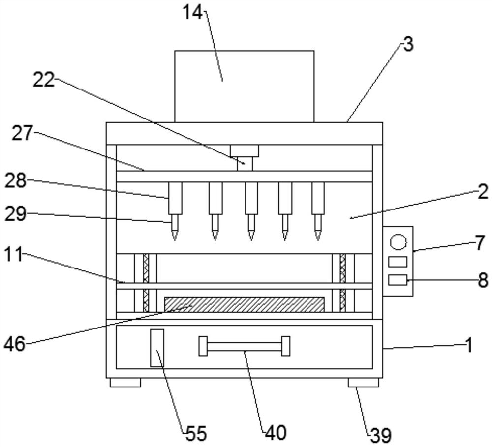
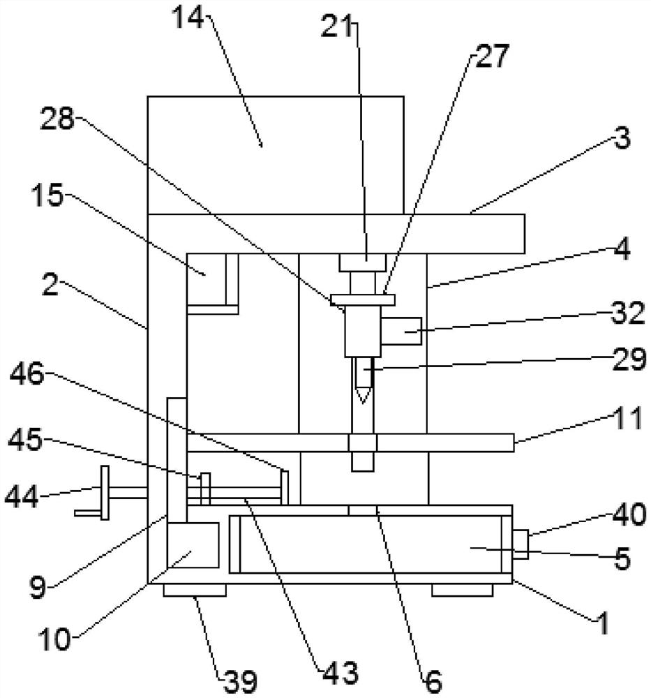
[0031] Such as Figure 1-8As shown, the punching device for financial data binding according to the embodiment of the present invention includes a support base 1, one end of the support base 1 is provided with a support plate 2, and the support plate 2 and the support base 1 are welded Fixed connection, the upper end of the support plate 2 is provided with a top plate 3, both sides between the support plate 2 and the top plate 3 are provided with side plates 4, and the middle part of the support seat 1 is flexibly connected with a set The material drawer 5, the two sides of the material collection drawer 5 are slidably connected between the slide rails and the support base 1, and the middle part of the upper end of the support base 1 is provided with several positioning holes 6, and the side plate 4 A control box 7 is arranged in the middle part of one side, and a plurality of control switch keys 8 are arranged on the control box 7, and a placement groove 9 is arranged at the ...

Embodiment 2

[0033] Such as Figure 1-8 As shown, both sides of the bottom end of the support base 1 are provided with support feet 39 , and the bottom ends of the support feet 39 are provided with anti-skid pads. A cabinet handle 40 is provided at the middle of the front end of the collection drawer 5 , and an observation window 55 is provided at one side of the collection drawer 5 . The positions of the through holes 13 and the positioning holes 6 are arranged at equal intervals, and the through holes 13 and the positioning holes 6 are exactly corresponding to the perforating pins 29 .

[0034] Such as Figure 1-8 As shown, both sides of the push plate 27 are provided with sliders 41, and the sliders 41 are located in a convex structure. Chute 42. The first motor 15 is fixedly connected to the support plate 2 through a connection frame 49 . The middle part of the support plate 2 is provided with a threaded rod 43, and one end of the threaded rod 43 is provided with a rod handle 44, a...


PUM


Abstract

The invention discloses a perforating device for binding financial materials. The perforating device comprises a supporting seat, a supporting plate is arranged at one end of the supporting seat, the supporting plate and the supporting seat are fixedly connected through welding, a top plate is arranged at the upper end of the supporting plate, a control box is arranged in the middle of one side of one side plate, and a plurality of control switch keys are arranged on the control box; an adjusting device is arranged in a containing groove, a rolling device matched with an inclined wheel is arranged at the side, located in a fixed box body, of a lifting rod, a clamping device connected with a clamping hole in a matched manner is arranged in the middle of one side of a mounting sleeve, and the clamping device comprises a fixed frame located at one side of the mounting sleeve; and a pulling block is arranged at the end, away from the mounting sleeve, of the fixed frame, and a spring is arranged at the position, located between a fixed ring and one end of the inner wall of the mounting sleeve, of a clamping pin. The perforating device has the beneficial effects that punching operation on the financial materials is achieved, uniform and tidy perforating on the financial materials is also achieved, dislocation is avoided, the structure is simple, and operation is convenient.

Description

technical field [0001] The invention relates to the technical field of financial data management, in particular to a punching device for binding financial data. Background technique [0002] Finance is not only the capital movement that exists objectively in the reproduction process of material materials in various departments and units of the national economy and the economic relationship embodied in the capital movement process, but more importantly, it is property and debt, that is, assets and liabilities. In financial work, there are many financial documents involved. In order to facilitate the storage and access of financial documents, it is often necessary to bind the financial documents. In the process of binding, we often need to punch holes in the documents. At present, many financial personnel are binding by hand, the material is thick and hard, punching is inconvenient, time-consuming and laborious, the punching is not neat, and it is easy to be injured. [0003]...

Claims


Application Information

Patent Timeline
IPC IPC(8): B26F1/24B26D5/08B26D7/02B26D7/26
CPCB26D5/086B26D7/02B26D7/2614B26F1/24
Inventor 不公告发明人
Owner 重庆丹含科技有限公司
Why Eureka
Try Eureka