Edge straightening machine convenient to overhaul and used for wood processing

A technology for easy maintenance and straight edge machine, which is applied in the field of wood processing and can solve the problems of increasing the grinding time of wood edges.

Inactive Publication Date: 2021-05-07
陆超林
View PDF0 Cites 1 Cited by
  • Summary
  • Abstract
  • Description
  • Claims
  • Application Information

AI Technical Summary

Problems solved by technology

[0003] If there are large bumps on the edge of the wood, and the bumps are in a triangular structure, it is easy to cause wood processing and easy maintenance. The high-speed operation of the sanding belt on the straight edge machine will directly tear off the triangular bumps, so that the broken triangular bumps will be easily broken. The edge of the wood is directly torn a deep hole, resulting in easy maintenance of wood processing

Method used


Image

  • Edge straightening machine convenient to overhaul and used for wood processing
  • Edge straightening machine convenient to overhaul and used for wood processing
  • Edge straightening machine convenient to overhaul and used for wood processing

Examples


Embodiment 1

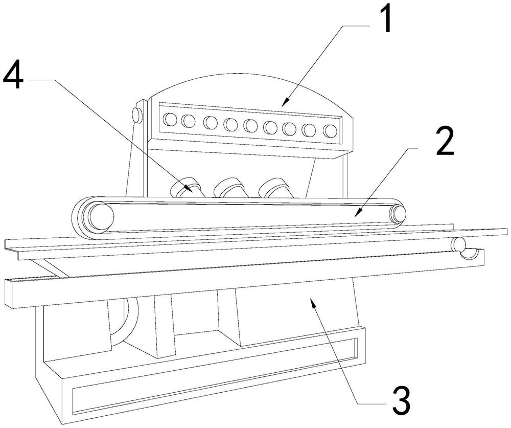
[0026] For example figure 1 -example Figure 5 Shown:

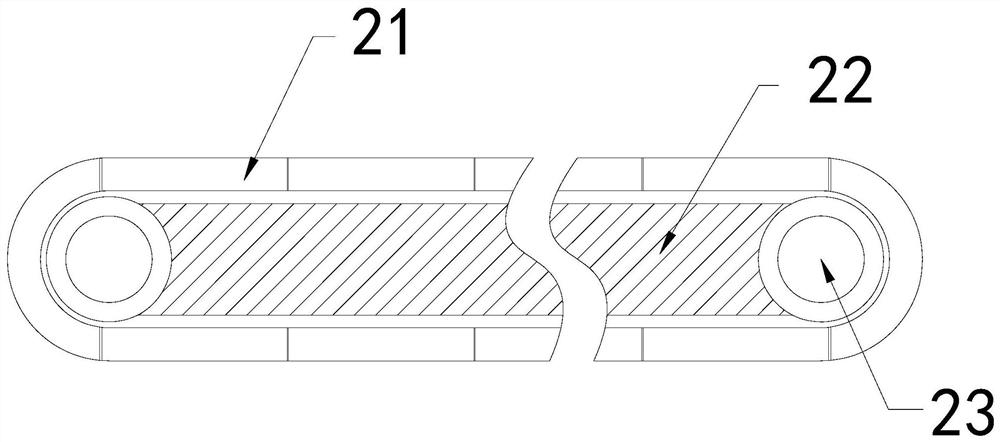
[0027] The invention provides a straight-edge machine for wood processing, which is convenient for maintenance. Its structure includes a control frame 1, a straight-edge mechanism 2, a base 3, and a driver 4. 4 is installed at the rear end of the straight side mechanism 2, the straight side mechanism 2 is connected with the control frame 1; The power roller 23 is movably engaged, and the connecting rod 22 and the power roller 23 are of an integrated structure.

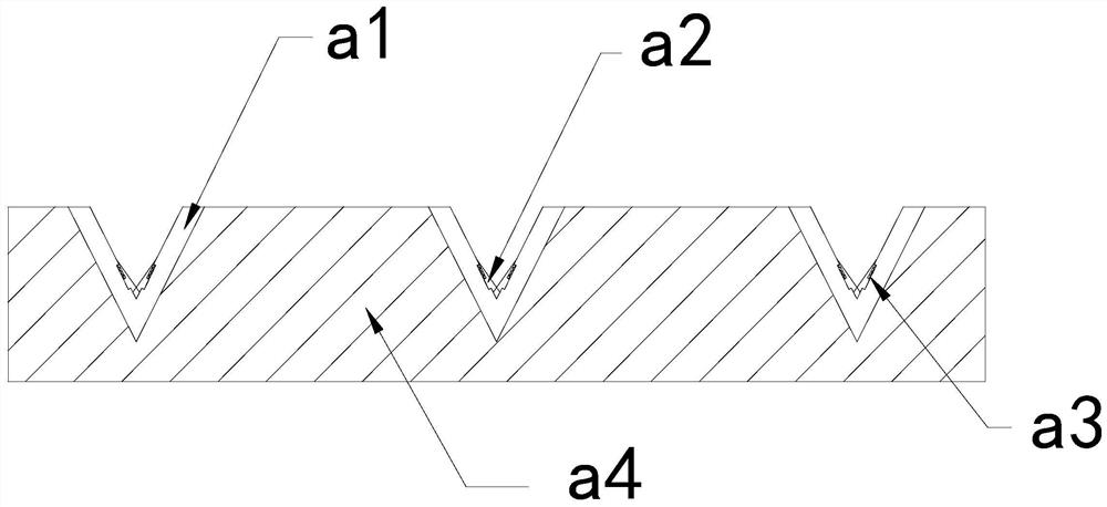
[0028] Wherein, the bearing surface 21 includes a guiding cavity a1, an extrapolating block a2, a pulling strip a3, and a plate body a4, the guiding cavity a1 is embedded in the inner position of the plate body a4, and the outer pushing block a2 and the guiding cavity a1 The inner side is movable and engaged, and the pull bar a3 is installed between the pusher block a2 and the guide cavity a1, and the guide cavity a1 has a triangular groove structure, which can...

Embodiment 2

[0034] For example Image 6 -example Figure 8 Shown:

[0035] Wherein, the pushing block a2 includes an extending block c1, a fitting plate c2, an engaging ring c3, ​​and a bottoming plate c4, the extending block c1 and the fitting plate c2 are in clearance fit, and the connecting ring c3 is installed on the extending block c1 Between the base plate c4 and the bonding plate c2, the base plate c4 and the bonding plate c2 are of an integrated structure. There are six overhanging blocks c1, and they are evenly distributed in parallel on the bonding plate c2. Through the connecting ring c3, ​​the The overhanging block c1 is pushed out.

[0036] Wherein, the overhanging block c1 includes a contact plate c11, a middle block c12, a bottom block c13, and a resilient piece c14. The contact plate c11 is movably engaged with the bottom block c13 through the middle piece c12. Between the bottom block c13 and the bottom of the contact plate c11, the upper layer of the contact plate c11...


PUM


Abstract

The invention discloses an edge straightening machine convenient to overhaul and used for wood processing. The edge straightening machine structurally comprises a control frame, an edge straightening mechanism, a base and a driver, the control frame is fixed at the upper end position of the base in an embedded mode, the driver is mounted at the rear end position of the edge straightening mechanism, the edge straightening mechanism is connected with the control frame, wood placed on the edge straightening mechanism is conveyed on a bearing surface, a triangular protruding block on the edge of the wood can enter a guide cavity, an outwards-extending cutter can extend outwards under cooperation of an elastic ring through vibration generated by polishing the edge of the wood through the bearing surface, therefore, a cutting piece can cut off the triangular protruding block, through pushing force generated by a connecting ring to an outwards-extending block, the outwards-extending block can extend outwards along an attaching plate, so that a contact plate can absorb moisture on the outer surface of the triangular protruding block, and the triangular protruding block can be pushed outwards by an outwards-pushing block.

Description

technical field [0001] The invention relates to the field of wood processing, in particular to a straight edge machine for wood processing which is convenient for maintenance. Background technique [0002] The straight edge machine for easy inspection and maintenance of wood processing is mainly used for grinding and smoothing the edge of wood. By placing the edge of the wood to be polished on the grinding belt on the straight edge machine for easy maintenance of wood processing, and then through the high-speed grinding belt Rotate, the edge of wood can be polished to smooth and straight, based on the above description, the inventor found that the existing straight edge machine for wood processing with easy maintenance mainly has the following deficiencies, for example: [0003] If there are large bumps on the edge of the wood, and the bumps are in a triangular structure, it is easy to cause wood processing and easy maintenance. The high-speed operation of the sanding belt o...

Claims


Application Information

Patent Timeline
Patent Type & Authority Applications(China)
IPC IPC(8): B27B5/04B27B31/00B27B5/29B27G19/02
CPCB27B5/04B27B5/29B27B31/006B27G19/02
Inventor 陆超林
Owner 陆超林
Why Eureka
Try Eureka